Troubleshooting
-
Ho
#8
0
#I7
0
#6
0
#I5
0.
#4
0
#3
0
#2
0
#’
0
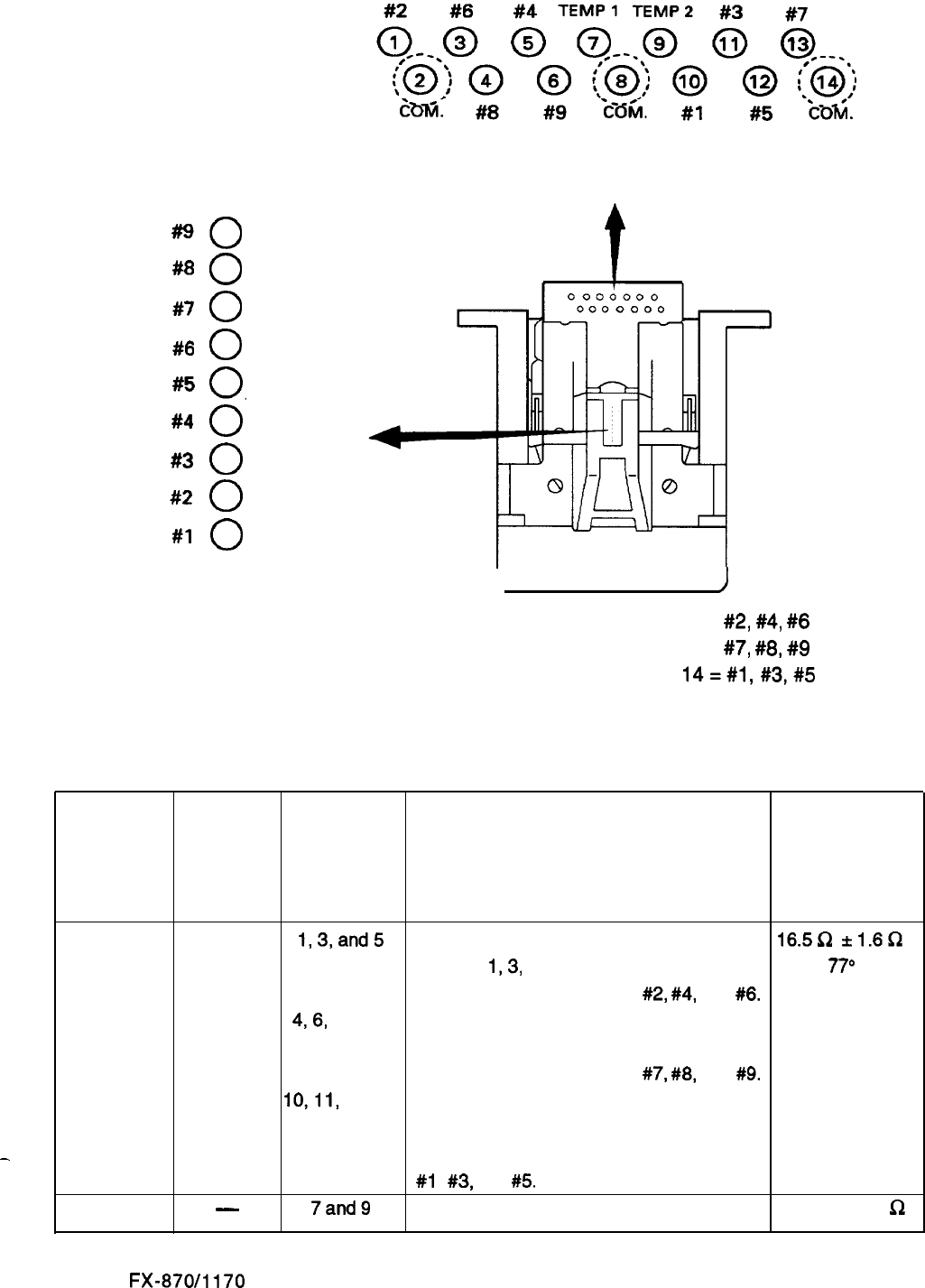
[TERMINAL ASSIGNMENT]
Note:
The printhead is
upside down in
this illustration.
[WIRE ASSIGNMENT]
1
Note: The commons correspond to the following
printhead dot wires:
J
COM. 2 =
#2,
#4,
#6
COM. 8 =
#7,
#8,
#9
COM.
14=#1,#3,#5
Figure 3-1. Printhead Resistance
Table 3-4. Printhead Test Points and Coil Resistance
Test Method
Common Connector
(Set Meter to Ohms. Disconnect
Connector
Pin
Test Pin
Printhead and Check it with
Number
Numbers
Numbers Printer Power Off.) Meter Reading
Printhead
2
1,3,and5
Place one lead on pin 2 and the other on
16.5&-I
*1.6S2
test pins
1,3,
and 5 to check the
(at
77”
F,
resistance of printhead dots #2, #4, and #6. 25” C)
8
4,6,
and 13 Place one lead on pin 8 and the other on
test pins 4, 6, and 13 to check the
14
Thermistor
-
resistance of printhead dots #7, #8, and #9.
10,i
1,
and 12
Place one lead on pin 14 and the other lead
on each of the test pins 10, 11, and 12 to
check the resistance of printhead dots
#l
,
#3,
and #5.
7and9
Place one lead on each pin.
Approx. 9.3 K
R
Epson
FX-870/1170
3-3


