C-14 / Appendix C - Hardware Installation Guide CI-ControlWave Express
subsequently start ControlWave Designer, it will operate only in ‘DEMO’ mode, and will
limit the available system resources.
IMPORTANT:
When you start ControlWave Designer, you will be reminded to register the
software. Unregistered software can only be used for a maximum of 30 days. For
more information on the registration process, see Chapter 2 of the Open BSI
Utilities Manual (document# D5081).
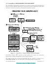
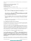
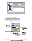
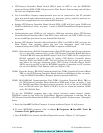
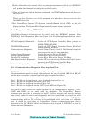
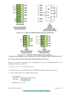
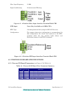
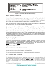
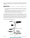
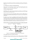
Step 3. Establish Communications using either LocalView, NetView, or TechView
and Run the Flash Configuration Utility
Communications must be established with the ControlWave Express using either
LocalView, NetView, or TechView.
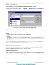
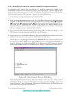
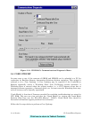
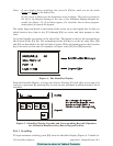
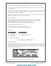
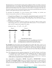
The ControlWave Express ships from the factory with a default Flash configuration. Most
users will need to edit this configuration to set the IP address (if using PPP), BSAP local
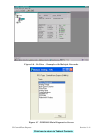
address, user accounts, and port parameters. This can be done in one of two ways:
• Either open the supplied Flash Configuration Profile (FCP) file and modify it, directly in
the Flash Configuration Utility, or in a text editor,
• Or retrieve existing Flash Parameters directly from the unit, and edit them in the Flash
Configuration Utility.
Detailed information on the Flash Configuration Utility and LocalView is included in
Chapter 5 of the Open BSI Utilities Manual (document # D5081). NetView is described in
Chapter 6 of that same manual. TechView is described in the TechView User’s Guide
(document# D5131).
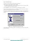
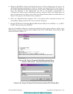
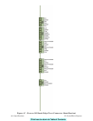
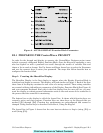
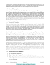
Step 4. Creation of the Application-Specific Control Strategy
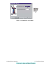
You can create your own application-specific control strategy using ControlWave Designer.
This involves opening a new project using the ‘CWMicro’ template, defining I/O points using
the I/O Configurator, and creating a program using one or more of the five supported IEC
61131 languages (FBD, ST, SFC, LD, or IL). Some of these languages are text-based, others
use graphical diagrams. The choice is up to you, depending upon your particular
application.
The ControlWave MICRO Quick Setup Guide (document # D5124) includes a simple LD
example. Additional examples are included in the manual, Getting Started with
ControlWave Designer (document # D5085). More detailed information about ControlWave
Designer and IEC 61131 is included in the ControlWave Designer Reference Manual
(document # D5088).
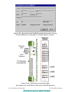
The ACCOL3 Firmware Library, which is automatically accessible through the template
referenced above, includes a series of function blocks which perform a variety of process
control and communication functions. These can be included within your program to
perform various duties including PID control, alarming, calculations, etc. Detailed
information about each function block is included in the ControlWave Designer on-line help
files.
Click here to return to Table of Contents