Component Replacement: Control Board
InfraStruXure InRow RC Service 51
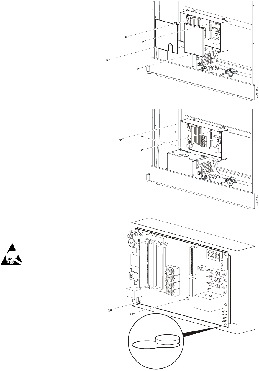
5. Remove the four T-20 screws from
the cover over the side of the
electrical/customer interface box.
Slide the cover up and off the box.
Tighten these screws to 15–20 in·lb
(1.7–2.3 N·m) upon reinstallation.
6. Disconnect the power cables, RJ-45
connectors, pressure tubes, and
other wire connections from the
board (refer to the board connection
diagram).
7. Remove the three T-20 screws
securing the electrical box to the side of
the unit (two on top, one on the front just
above the rectifiers), and rotate the
electrical box so that you can access the
board.
8. Remove the two #1 Phillips screws
securing the board to the electrical
box.
9. Slide the board towards the rear of
the box and then pull it off the seven
keyhole standoffs securing it to the
box.
10. Reverse the procedure to install the
new board. Tighten screws to 4–5
in·lb (0.5–0.6 N·m) of torque.
11. Reinstall the electrical box, and
tighten the T20 screws to 15–20 in·lb
(1.7–2.3 N·m) of torque.
Follow appropriate
electrostatic discharge
precautions when
handling circuit boards.
na2115a


