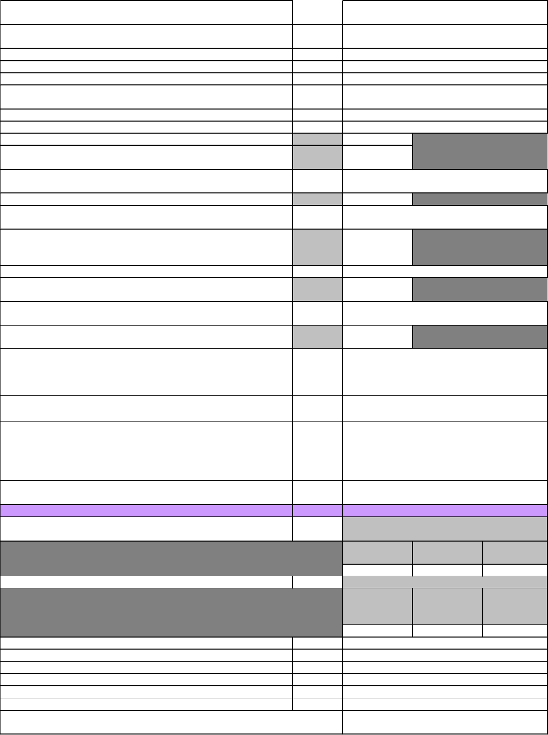
Service Procedures: Start-up Site Form
InfraStruXure InRow RC 23
2. Is the unit connected to an existing building Chilled Water loop or a
dedicated Chiller/pump system?
3. Is there a strainer installed in the Chilled Water supply line to the RC or
to the supply piping to the CDU?
4.
Isolation valves are present and open at the RC and or CDU?
5. Is Pex-Al-Pex tubing being used with the RC
6. Was the Pex-Al-Pex tubing installed by APC?
7. Was the Pex-Al-Pex tubing installed per the installation manual?
(Document number 990-2823)
8. Is the Chilled Water piping Insulated
9. Has the air been bled from the unit and Chilled Water line sets?
10.
What is the Chilled Water supply temperature to the unit? Temp:
11. What is the Chilled Water set point for the Chiller supplying Chilled
Water to the unit? Tem
12. Will the current Chilled Water Set point provide maximum capacity for
the unit per the Technical Data?
Document 990-2846
13. What is the Chilled Water flow to the unit? GPM:
14. Will the current Chilled Water flow provide maximum capacity for the
RC per the Technical Data?
Document 990-2846
15. Base on the RC's being fed by the CDU what is the total GPM through
the CDU?
Maximum GPM throu
h a CDU must not exceed 175 GPM
GPM:
16. Is glycol being used in the Chilled Water loop?
17. What is the concentration of glycol in the system?
% of
Glycol:
18. The condensate removal piping is installed for the RC and or CDU?
CDU Condensate pipin
is optional
19. What is the height of the RC condensate piping? Per the installation
manual
Document 990-2402
the maximum lift is 16 feet. Hei
ht
20.
Are the 2 factory mounted NTC Sensors used to measure incoming
Chilled Water and leaving Chilled Water properly inserted into their sensing
wells on the Suppl
& Return Chilled Water lines of the RC?
21. Are the 4 sensors (2 Supply & 2 Return) measuring Supply and Return
air mounted in their proper locations from the factor
?
22. Is the remote sensor located in one of the customers racks sensing the
inlet air temperature? (Sensor needs to be installed regardless of Control
Configuration: In-Row, HACS, RACS. Sensor should be located in the air
stream in the front of the Rack in the Upper 1/3 of the Rack
.
23. Is the optional water detection device properl
routed and connected
Electrical Checks: Yes/No
1. Do the field circuit breakers for Main Power "A" and Main Power "B"
match unit name plate?
Unit Amp Ratin
Unit Power
"A
Unit Power "B
2. Does Power Supply "A" & "B" voltage match Unit nameplate
Unit Voltage
Ratin
Unit Power "A"
Volta
Unit Power "B"
Volta
3.
Is the unit properly grounded?
4. Is a BMS (Building Management System) system being used
5. Is the BMS wiring connected to the unit properly?
6. Does the last unit in the BMS wiring have a terminator installed
7. Are the common alarm contacts being used?
8
. Are the remote shutdown contacts being used?
Record Name Plate voltage info and actual
Comments:
Record Name Plate info and actual power feed
Circuit Breaker sizes supplied in the field
9. Which DC signal is being used for the remote shutdown signal 12 vdc / 24 vdc?
