


Model 780-95 Page 3
© 2003 Xantech Corporation
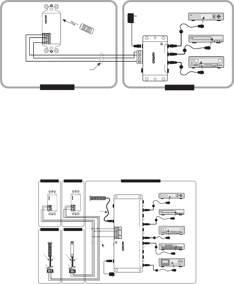
APPLICATION WIRING
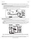
A typical system, with a 780-95, 781RG Power Supply and 283M Emitters plugged into a 789-44 Connecting Block, is shown in
Figure 3:
1. Wire the appropriate leads of the 3 or 4-conductor cable from the 780-95 to the +12VDC, GND, STATUS (if applicable), and IR
IN terminals on the 789-44 Connecting Block
2. Plug in the 3.5mm mono mini plug from any of the 282, 284, 283 and 286 series Emitters into the jacks labeled EMITTERS on
the 789-44 Connecting Block and affix the opposite end to the IR Sensor Window of the controlled equipment.
3. Plug in the 2.1mm Coaxial power plug of the 781RG Power Supply (not included) into the jack labeled 12VDC on the 789-44
Connecting Block.
4. Plug the AC end of the 781RG power Supply into an ‘un-switched’ 120VAC outlet.
IR OUT
GND
STATUS
+12V
283M
Blink-IR
Mouse Emitter
To 120 V AC
(unswitched)
781RG
Power Supply
789-44
Connecting Block
283M
Emitter
283M
Emitter
REMOTE ROOM
MAIN ROOM
Hand Held
Remote
VCR
GND
IR
OUT
+12V
780-95
Plasma-Friendly
J-Box
IR Receiver
(rear view)
3-Conductor
Inter-room Cable
(unshielded OK)
780-95
IR RECEIVER
®
12VDC
+12
VDC
GND
STATUS
IR IN
EMITTERS
IR
RCVR
789-44
CONNECTING BLOCK
®
Satellite Receiver
AV Receiver
Figure 3 - Typical System Layout using 780-95, 789-44, 781RG, and 283M Emitters
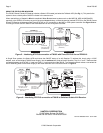
ADVANCED WIRING CONFIGURATION
780-95 may also be used in conjunction with other Xantech IR Receivers by simply wiring in parallel on a Connecting Block such as the
791-44 Amplified Block as shown in Figure 4 below.
1. Connect all IR Receivers in parallel at the terminals of the connecting block as shown in Figure 4 below.
2. Plug in the 2.1mm Coaxial power plug of the 781RG (or 782) Power Supply (not included) into the jack labeled PWR on the
789-44CB.
NOTE: Up to 7 IR Receivers may be connected in parallel with a single 781RG power supply. If more IR Receivers or any Keypads
are required, check total current requirements and increase power supply current rating accordingly; i.e. 782-00 - 1.2A power
Supply)
3. Plug in the Emitters 3.5mm mono mini plug (282, 284, 283 or 286 series) into the Emitter Outputs on the 791-44.
283M
Blink-IR
Mouse Emitter
To 120 V AC
(unswitched)
781RG
Power Supply
283M Emitter
283M Emitter
283M Emitter
283M Emitter
VCR
Cassette DecK
GND
+12V
490-00
Series
Micro Link
IR Receivers
3-Wire
Cable
IR
OUT
GND
+12V
Red
Stripe
3-Wire
Cable
IR
OUT
GND
+12V
480-00
Dinky Link
IR Receiver
Red
(or white)
Stripe
REMOTE ROOM 1
780-80
CFL-Friendly
J-Box IR Receiver
780-95
Plasma-Friendly
J-Box IR Receiver
7 Foot 3-Conductor
Cable with Quick
Connect Stereo
Mini Plug
490-30
Series
Micro Link
IR Receivers
MAIN ROOM, EQUIPMENT AREA, ETC.
REMOTE ROOM 2
REMOTE ROOM 3 REMOTE ROOM 4
GND
IR
OUT
+12V
3-Conductor
Room-to-
Room Cables
(Home Runs)
IR OUT
GND
STATUS
+12V
791-44
Amplified Connecting Block
780-80
IR RECEIVER
®
780-95
IR RECEIVER
®
Satellite Receiver
AV
Receiver
CD Changer
+12 VDC
GND
EMITTERS
12 VDC
HIGH
IR
OUT
STATUS
IR IN
IR
RCVR
791-44
AMPLIFIED
CONNECTING BLOCK
®
IR
OUT
IR OUT
GND
STATUS
+12V
Figure 4 - Advanced Wiring Configuration using 780-95, 791-44, 781RG Power Supply and multiple 283M’s
CAUTION: With any of these systems, be sure the 781RG (or 782-00) Power Supply is plugged into an un-switched AC outlet. This
maintains the 780 system in "stand-by" operation so that power-on commands can be sent to the controlled equipment.