


4
NOTE
INSTALLATION (cont’d)
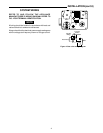
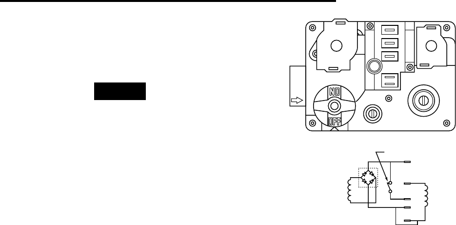
SYSTEM WIRING
REFER TO AND FOLLOW THE APPLIANCE
MANUFACTURER’S WIRING DIAGRAM. REFER TO
FIG. 4 FOR TERMINAL IDENTIFICATION.
All wiring should be installed in accordance with local and
national electrical codes and ordinances.
Always check that the electrical power supply used agrees
with the voltage and frequency shown on the gas control.
PILOT ADJ
Figure 4. Gas valve wiring diagram
5
1
4
2
3
Rectifier
Bridge
Main
Redundant
Pressure
Switch
3
2
4
1
5