


3
NOTE
INSTALLATION
1. Turn off electrical power to the system at the fuse box
or circuit breaker. Also turn off the main gas supply.
2. If replacing an existing valve, disconnect all plumbing
and electrical connections from the old control.
3. The control may be installed in any position, except
upside down. The arrow on the bottom plate indicates
the direction of gas flow through the valve.
4. You should use new pipe that is properly chamfered,
reamed, and free of burrs and chips. If you are using
old pipe, be sure it is clean and free of rust, scale,
burrs, chips, and old pipe joint compound.
5. Apply pipe joint compound (pipe dope) or teflon tape
that is approved for all gases, only to the male
threads of the pipe joints. DO NOT apply com-
pound or teflon tape to the first two threads (see fig. 3
for typical piping connections).
6. If you are using a vise or open-end wrench to hold the
valve while installing piping, do not tighten exces-
sively, as this may damage the valve.
7. See SYSTEM WIRING when making electrical con-
nections. After all gas and electrical connections are
completed, turn gas on and check for gas leaks with
leak detection solution or soap suds. Bubbles forming
indicate a leak. SHUT OFF GAS AND FIX ALL
LEAKS IMMEDIATELY.
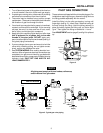
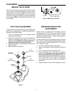
PILOT GAS CONNECTION
These valves are shipped with the pilot outlet plugged. For
installations requiring pilot gas, remove the plug and use
the fitting packed separately with the control.
Install the fitting into the pilot gas tapping, turning until
finger-tight (see fig. 2). Insert clean, deburred tubing all
the way through the fitting. Hold the tubing securely in
place and slowly tighten the fitting until you feel a slight
“give”. Then tighten the fitting an additional 1
1
⁄2 turns.
See ADJUSTMENT section (page 5) and fig. 6 for pilot set
up.
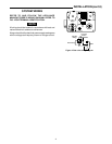
PILOT
OUT
PRESS
TAP
Pilot Gas
Outlet
Figure 2
Main Gas
Outlet
Pressure
Tap
Regulator
Vent
Piped Gas
Supply
Piped Gas
Supply
Tubing Gas
Supply
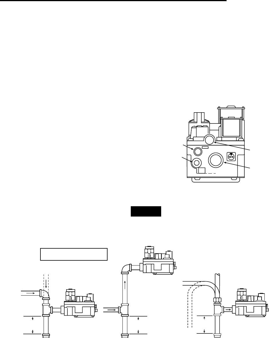
NOTE: ALWAYS INCLUDE A
DRIP LEG IN PIPING
Figure 3. Typical gas valve piping
Horizontal
Drop
Gas Valve
3 in.
minimum
Gas Valve
Riser
3 in.
minimum
Drop
Horizontal
Riser
Gas Valve
3 in.
minimum
All piping must comply with local codes, ordinances,
and/or national fuel gas codes.