


Whistler’s ergonomic and user-friendly design
p
rovides a new level of operating convenience. Special
features include:
Note: Not all units have all features listed.
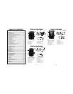
1. Bracket Release Button –
provides quick
and easy release of the mounting bracket.
2. Speaker – provides distinct audio warnings
f
or X, K, Ka band radar, safety radar, laser
and VG-2.
3. M
ounting Bracket Location
– slot holds
m
ounting bracket firmly.
4. R
adar Antenna
– compact, high-eff
iciency
antenna receives radar signals.
5. Front Laser – high gain optical lens
provides increased sensitivity and field of
view for leading-edge laser detection.
6. Rear Laser – an integrated optical
waveguide provides superior detection of
laser signals transmitted from behind.
7. City Button - reduces the annoyance of
false alerts typically encountered in urban
driving areas.
8. Quiet Button - pressing QUIET before a
radar signal is detected engages Auto
Quiet Mode which provides “clicking”
sounds after the initial warning. Pressing
QUIET during a radar encounter silences
audio alerts, while allowing visual alerts to
keep you informed.
9. Power / Volume Control – turns unit on/off
and adjusts audio level.
10. Dim Dark - engages Dim/Dark modes
11. Menu Button - (XTR-145) turns VG2 on/off.
(XTR-265/335) enters option select mode.
12.
Icon Display -
of
fers easy-to-r
ead display to
indicate power, city mode, radar band
identification, and signal strength.
FEATURE DESCRIPTIONS
12a. Numeric Icon Display (XTR-265/335)
c
ombines icon display with a 7 segment digital
display that shows signal strength indication
and band identification.
1
2b. Dual Alert LED Periscope -
p
rovides
additional visual alerts.
13. VG-2/Laser Icon – indicates the unit is
receiving V
G-2 or laser signals.
14. X-band Icon - indicates the unit is receiving
a X-band signal.
1
5. K-band Icon -
i
ndicates the unit is receiving
a K-band signal.
16. Ka-band Icon - indicates the unit is receiving
a Ka-band signal.
17. H - indicates unit is in Highway mode.
18. C - City Icon - indicates that the unit is
operating in city mode.
19. Signal Strength Icon - indicates the strength
of the signal being detected.
20. K/Ka-band Icon - shows the unit is receiving
a K or Ka band signal. K/Ka indicator will
flash for Ka band.
21. V - indicates that the unit is receiving a
VG-2 signal. Indicates that VG-2 is
engaged.
22. L - indicates that the unit is receiving a laser
signal.
•
Total Band Protection
™
- Complete Band
Coverage that detects laser, radar, VG-2 and safety
radar bands.
FEATURE DESCRIPTIONS
56
Mounting Guidelines
•
Mount the unit as low as possible near the center of
t
he windshield.
•
Do not mount the unit behind wipers, ornaments,
mirrored sunscreens, etc. These obstructions have
metal surf
aces which can affect radar and laser
signals and reduce critical warning time.
(Regular tinted glass does not affect reception.)
•
Some windshields have an Instaclear
™
or Electriclear
™
t
ype coating, which affects radar signals. Consult
your dealer or the owner’s manual to determine if
your windshield has this coating.
•
Avoid placing unit in direct contact with the wind
shield.
•
To reduce the possibility of theft, conceal the unit
when not in use.
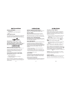
Windshield Mounting
•
Install the two suction cups and rubber bumper onto
the bracket by fitting them into their holes.
•
Press the suction cups onto the windshield at the
location you have chosen.
IMPORTANT: Some newer cars have a plastic
safety coating on the inside of the windshield. The
windshield bracket may leave permanent marks on
this type of surface.
To find out if your vehicle has this
type of windshield, check the owner’s manual or ask
your dealer. We recommend that you do not leave
the suction cup bracket on the windshield in direct
sunlight. If the detector is removed, this may cause
blistering of the dash in some vehicles.
INSTALLATION
7