


WHISTLER FEATURES FEATURE DESCRIPTIONS
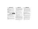
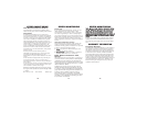
Installation
• Locate the tab near the button openings and
insert this end first into the unit.
• Gently snap in the other tabs as you work your
way to the back of the unit.
Mounting Guidelines
• Mount the unit as low as possible near the center
of the windshield.
• Do not mount your unit behind wipers,
ornaments, mirrored sunscreens, etc. These
obstructions have metal surfaces which can affect
radar and laser signals and reduce critical warning
time. (Regular tinted glass does not affect
reception.)
• Some windshields have an Instaclear
™
or
Electriclear
™
type coating, which affect radar signals.
Consult your dealer or the vehicle’s owner’s manual to
determine if your windshield has this coating.
• Avoid placing unit in direct contact with windshield.
• Avoid placing unit in direct sunlight.
• To reduce the possibility of theft, conceal your
unit when not in use.
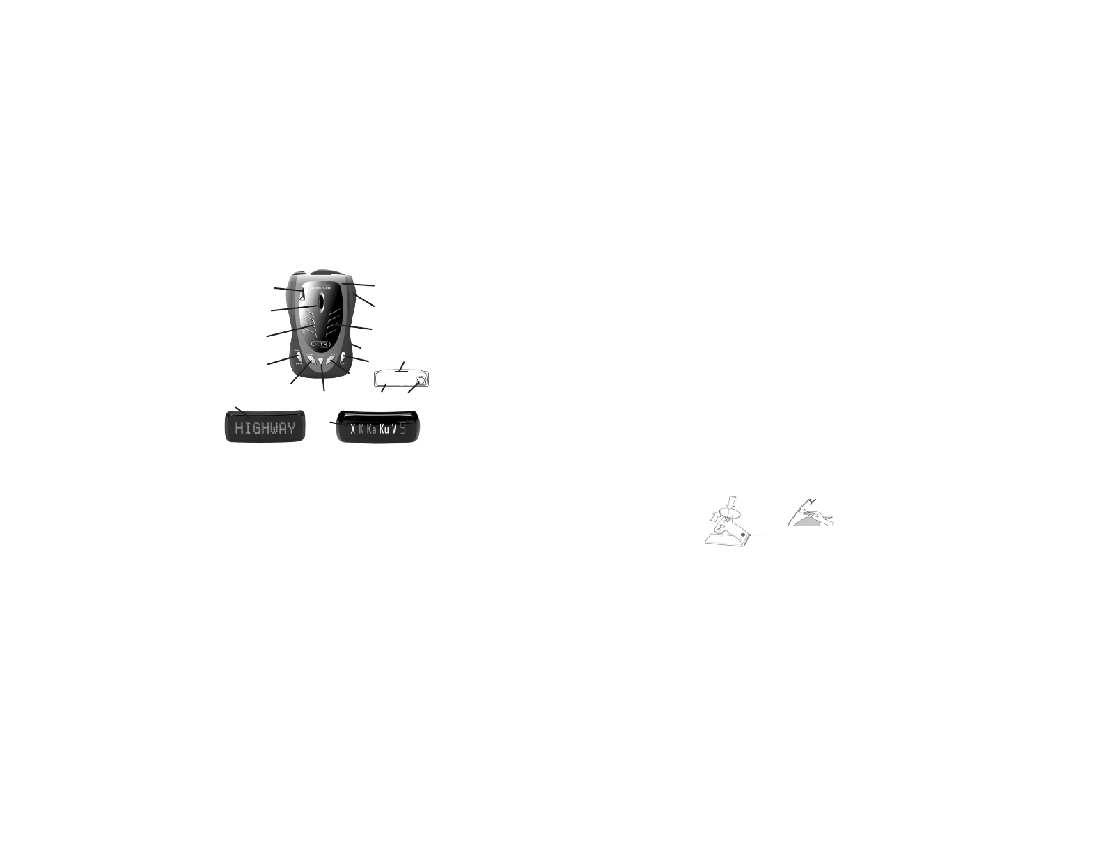
Windshield Mounting
• Install the two suction cups and rubber bumper
onto the bracket by fitting them into their holes.
•
Press the suction cups onto the windshield at the
location you have chosen.
• Slide the detector onto the bracket until it locks into
place.
• If necessary, the unit may be leveled by bending the
windshield bracket.
• Press the bracket release button and remove the
detector before bending.
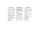
INSTALLATION
1
9
11
10
2
6
4
5
3
7
13
Accessories:
Windshield Bracket Kit, Straight Power Cord & 2 Trim Rings
12a
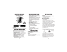
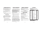
XTR-325/425/560
6. Rear Laser Antenna – An integrated optical
waveguide provides superior detection of laser
signals transmitted from behind.
7. City Button - Reduces the annoyance of false
alerts typically encountered in urban driving areas.
8. Quiet/Menu Button - Pressing QUIET before a
signal is detected engages Auto Quiet Mode.
Pressing QUIET during a radar/laser encounter
silences audio alerts.(Pressing and holding for 2
seconds allows you to enter Option Select Mode—
see page 13)
9. Power/Dim -Turns unit on/off and engages
Backlight settings (press and hold).
10. Volume Down Button – Adjust volume down.
11. Volume Up Button – Adjust volume up.
12a. Blue Backlit LCD Programmable Text
Display – Provides distinct visual confirmation of
signals detected, signal strength, and indicates
engaged modes of operation.
12b. Seven Segment Icon Display – Provides band
and numeric signal strength indicators
13. Power Jack – Provides connection for the power
cord.
14. Removable Trim Ring – Allows changing the trim
ring to one of the other colors.
15. External Audio Jack – Permits easy connection of
an external speaker/headset to the XTR 560.
16. Microphone – Allows recording of audio tones in
model XTR-560
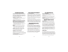
INSTALLATION
Trim Ring Removal/Installation
To change the trim ring to another color, follow
these simple steps:
Removal
• Locate the tab on the trim ring at the top of
the mounting bracket location.
• Using your fore finger, lift up on the trim ring
and the ring will pop out.
8
Windshield
Mounting
34
Rubber Bumper
2
14
12b
XTR-325XTR-425/560
FEATURE DESCRIPTIONS
NOTE: Not all units share all the features listed
Whistler’s ergonomic and user-friendly design pro-
vides a new level of operating convenience.
Special features include:
1. Bracket Release Button – Provides quick and
easy release of the mounting bracket.
2. Speaker – Provides distinct audio warnings for
X, K, Ka, Ku band radar, safety radar, laser and VG-2.
3. Mounting Bracket Location – Slot holds
mounting bracket firmly.
4. Radar Antenna – Compact, high-efficiency
antenna receives radar signals.
5. Front Laser Antenna – High gain optical lens
provides increased sensitivity and field of view for
leading-edge laser detection
16
15