


9
RULES FOR CONNECTOR
PIPE INSTALLATION
1. The crimped end of the chimney connector fits
inside the furnace flue collar. Install additional chim-
ney connectors and elbow with the CRIMPED END
TOWARD THE FURNACE. This will allow any
condensation in the flue to run back into the furnace.
Use 6" dia. steel pipe and elbows for connection to
chimney. Never use less than 24 gauge and al-
though blued steel is satisfactory, high temp painted
black is much more desirable.
2. Slope any horizontal pipe upward toward the
chimney at least 1/4 inch for each foot of horizontal
run.
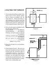
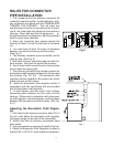
3. You must have at least 18 inches of clearance
between any horizontal piping and the ceiling.
(See Fig. 3)
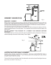
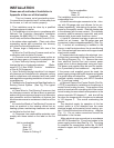
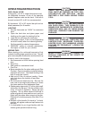
4. The chimney connector must not extend into the
chimney flue. (See Fig. 6)
5. Seal each chimney connector pipe joint with fur-
nace cement. Also seal the pipe at the chimney.
6. Use 3 sheet metal screws at each chimney pipe
joint to make the piping rigid.
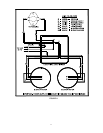
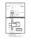
7. The chimney connector may include a section for
a barometric draft regulator between the furnace and
the chimney (Fig. 4,5, &7). The barometric draft
regulator must be installed in the same room (same
pressure zone) as the furnace.
8. Install the barometric draft regulator strictly in
accordance with the instructions that are provided
with the barometric draft regulator.
9. A solid damper must be used in the chimney
connecting pipes between the flue collar and the
chimney. When used in conjunction with a baromet-
ric draft regulator, the solid damper must be placed
between the barometric and the chimney. (See Fig.
4,5,7)
Adjusting the Barometric Draft Regula-
tor
1. Drill a hole in the chimney connector within 18" of
the flue collar below the barometric draft regulator
just large enough for the tube of the manometer.
2. Build a fire after all chimney connections have
been made.
3. Use a manometer to measure the draft in the flue.
4. Adjust the Barometric Draft Regulator to obtain a
draft of 0.05 - 0.06" W.C. under stable fire conditions.
RIGHT WRONG WRONG
Fig. 6
Fig. 7