


10
ASSEMBLY OF FURNACE
Your furnace requires the following items
to be assembled or installed by the service
person:
Feed Door Pull Handle
Feed Door Locking Handle
Blower(s) and Blower Controls
Electrical Connections
Remove all parts from inside the furnace
and inspect for damage, including the
firebrick as some breakage could occur
during shipment.
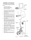
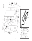
Assemble the feed door pull handle as
shown in Figure 8.
Attach feed door locking handle as in
Figure 9 with screws and nuts provided.
Note: Slotted holes are for adjustment of
handle. Adjust handle until some pres-
sure is required to lock feed door during
firing sequence.
Install the thermodisc on rear of furnace
cabinet with the two screws provided.
Mount the conduit assembly from the junc-
tion box to the thermostat bracket. Crimp
the two female terminals to each of the
wire leads. Plug the wires to the
thermodisc. NOTE: It does not matter
which of the two wires plugs to which
terminal on the thermodisc.
Remove blowers from cartons. Remove
junction box cover. Attach clip nuts as
shown in figure 10. Install blowers and
gaskets with 1/4"-20 x 3/4 bolts as shown.
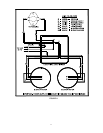
Wire right side blower first (See wiring
diagram, Fig. 11) and replace cover on
junction box on blower.
Wire left blower same as above and re-
place cover.
Check operation of shaker grates with
grate handle before operating furnace.
1.
2.
3.
4.
5.
6.
7.
8.
Fig. 10
Fig. 9
Fig. 8
Factory
Installed