TOSHIBA
6F9EOlll
1.
2.
3.
4.
5.
6.
7.
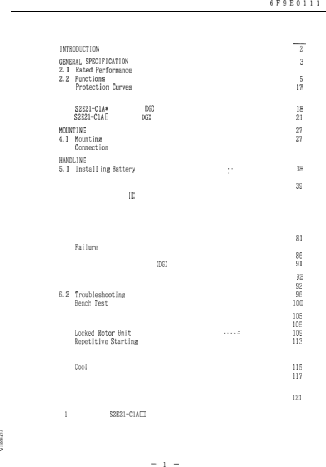
CONTENTS
Page
*N*ROD”CT[ON
........................................................
-j-
GENERA,,
SpECIF~CAT]ON
................................................
3
2.1
Rat,&
Performance
..............................................
4
2.2
Functions
......................................................
5
2.3
Pr,ot~tion
Curves
..............................................
17
APPEARANCE AND CONFIGURATION
........................................
18
3.1
SZEZl-ClA*
(without
DG)
.......................................
18
3.2
S2.E21-ClA[
1 (with
DG)
........................................
21
MODNTlNO
AND CONNECTION
.............................................
27
4.1
MolJnting
.......................................................
27
4.2 Co~yj&ion
.....................................................
30
HANDLING
............................................................
38
5.1
lnijtal1
ing
Battery
..........................
:.
.................
38
5.2 Turning Power On
...............................................
38
5.3 Basic Operation of Screen
......................................
39
5.4 Registration of
ID
.............................................
44
5.5 Menu
...........................................................
46
5.6 Measurement
....................................................
47
5.7 Event
..........................................................
54
5.8 Setting
........................................................
56
5.9 Testing
........................................................
81
5.10
Failure
Information
............................................
83
5.11 Hand1 ing of Memory Card
........................................
86
5.12 Directional Ground Unit
(DG)
...................................
91
MAINTENANCE AND INSPECTION
..........................................
92
6.1 Periodic Inspection
............................................
92
6.2
Troubleshooting
.................................................
96
6.3
Berlch
Test
......................................................
I,,,,
PROTECTIVE DETECTION SCHEME
.........................................
105
7.1 Overload Unit
..................................................
105
7.2
Locfked
Rotor
hit
...........................
..-.c
...............
109
7.3
Reptitive
Starting
.............................................
113
7.4 Detection of Starting Current and Starting Time
.................
114
7.5 Detection of the Heating Time Constant and
Cocli
ing Time Constant
...........................................
115
7.6 Setting Based on Fundamental Information
........................
117
7.7
Setting For Reduce Voltage Starting .............................
120
APPENDIX A
. . . . . . . . . . . . . . . . . . . . . . . . . . . . . . . . . . . . . . . . . . . . . . . . . . . . . . . . . .
121
Rev
1
TYPE
S2E21-ClAU
VERSION 1.01
2
2
g
>
-l-


