


LF470/LF622
2
MAX:17W(24VA) with PROFIBUS
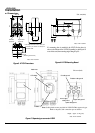
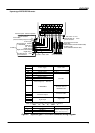
Model LF470 Detectors
Fluid pressure: -0.1 to 1 MPa
Pipe connection port:
Standard – Rc (PT) 1/4 thread
Option – See Table 4
Principal materials:
Measurement tube – Alumina ceramics
Electrodes – Platinum
Pipe connection port:
Standard – 316 stainless steel
Option –
Ti (titanium)
Polyvinyl chloride (shock-resistant)
+ Ta (Tantalum) for grounding plate
Polyvinyl chloride (shock-resistant)
+ Pt-Ir for grounding plate
Hastelloy C (Equivalent)
Dedicated preformed cables:
Signal cable – 2-wire shielded chloroprene
sheathed cable
Overall length: 7mm
Length: 5m
Excitation cable – 3-wiren chloroprene cable
Overall length: 7mm
Length: 5m
Coating: Pthalic acid resin coating pearl-gray
colored
Mass: approximately 1.0 kg (2.2 lb)
(for each size excluding cables)
Model LF622 converters
Input signals
Analog signal — the voltage signal from detector,
proportional to process flow rate (for LF622
separate type converter).
Digital input DI
Signal type: 20 to 30Vdc voltage signal
Input resistance: 2.7k
Number of inputs: one point
Note: DI cannot be used with the Modbus
communication.
DI function — One of the following functions can
be assigned to the optional DI signal.
Range switching — Selects either the higher or
lower range in the unidirectional or
bidirectional 2-range setting.
Totalizer control — Starts and stops the built-in
totalizer.
Fixed-value outputs — Outputs fixed-values for
current and pulse outputs.
Zero adjustment — Executes zero adjustment
(on-stream at zero flow rate).
Output signals
Current output:
4–20mAdc (load resistance 0 to 750)
Digital outputs — Two points optionally
available as follows.
Digital output DO1 :
Output type: Transistor open collector
Number of outputs: One point
Output capacity: 30Vdc, 200mA maximum
Note: DO1 cannot be used if Modbus
communication connection is 3 lines.
Digital output DO2 :
Output type: Solidstate relay output (non
polarity)
Number of outputs: One point
Output capacity: 150Vdc, 150mA maximum or
150 V ac (peak to peak), 100mA maximum
Note: DO2 cannot be used with the Modbus
communication.
DO1 and DO2 functions — One of the following
functions can be assigned to DO1 and/or DO2
• Pulse output (available only for DO1,DO2)
Pulse rate: Max 10kHz (10,000pps) (DO1)
Max 100Hz ( 100pps) (DO2)
(Over 1kpps, auto-setting)
Pulse width: 0.3 to 500ms (but less than half of
the period for 100% flow rate)
Note: The same and simultaneous pulse is not
available between DO1 and DO2.)
• Multi-range selection outputs (Note 1)
• High, High high, Low, and/or Low low alarm
outputs (Note 2)
• Empty pipe alarm output (Note 2)
• Preset count output
• Converter failure alarm output (Note 2)
Note 1: Two outputs (DO1 and DO2) are needed for
4-range switching and forward/reverse
2-range switching.
Note 2: Normal Open (default set) or Normal Close
is selected for alarm outputs when
programming.
When power failure occurs, unit will be fault to
Normal Open