


LF470/LF622
6
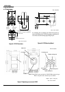
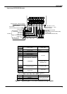
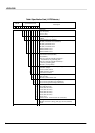
Wiring Precautions
(1) Connect the following two cables correctly:
1) signal cable (on the right facing the LF470)
2) excitation cable (on the left facing the LF470)
See figure3.
(2) Do not bend apply excessive force to these cables.
(3) DO1, DO2 (opt.), and DI (opt.) use the same
common terminal (COM). This COM can not
connect to other equipments which have their
own ground terminal. (Power supply for
connecting to DI or DO, etc…) Need to wire
separately.
Wiring Precautions (PROFIBUS or Modbus)
(1) For wiring path, avoid places near electrical
equipment that may cause electromagnetic
induction or electrostatic induction interference
(such as a motor, transformer and wireless
transmitter).
(2) Use a PROFIBUS-PA cable or a RS485 twist-pair
cable for signal cable. In addition, make sure to
use a shielded cable to improve noise resistance.
Furthermore, installation of signal cable in metal
conduit is recommended.
(3) General cables are designed for indoor use where
cables are not exposed to humidity, rain, etc.
When you install cables, make sure to check the
operating conditions such as the operating
temperature range of the cable by contacting its
manufacturer.
(4) When you carry out cable end treatment of cable,
use a dedicated cable stripper etc. so that the core
wire of the cable will not be nicked or damaged.
In addition, for cables, be careful of allowable
maximum bend diameter etc. (Basically, do not
install cables in a way cables are twisted or bent.).
(5) Consider installing a PROFIBUS-PA arrester in
the communication path of PROFBUS-PA so that
the electromagnetic flowmeter will not be affected
by lightning etc.
(6) The electromagnetic flowmeter is not equipped
with terminating resistors. Use the terminating
resistor unit for PROFIBUS-PA or junction box,
if necessary.
(7) Only one PROFIBUS-PA cable goes through a
cable gland of the Electromagnetic Flowmeter.
Please use the junction box at system
configuration.
(8) Install a terminator to flowmeter that connected to
end of Modbus network.
Piping Precautions
(1) Connect the fluid pipe to the pipe connection port
using a joint that matches the Rc (PT) female
screw. Use seal tapes when connecting the pipe to
the port to prevent a fluid leakage. Do not tighten
the connection screw too much.
(2) Design piping so that the detector’s pipe is always
filled with the fluid to be measured, whether the
fluid is flowing or not.
(3) The fluid to be measured must be held still in the
pipe when the LF470 is being adjusted. If the fluid
can not be stopped after the LF470 installation,
install a bypass pipe in parallel with the LF470
flowmeter.
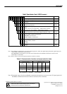
Meter size
To select the meter size:
See Table 1 to 2 and find meter sizes within the
velocity of 0.1 to 10m/s (0.3 to 32.8 ft/s) for a
specified full-scale (measuring range high limit)
flow. Select one that has its full-scale velocity
between 1 and 3m/s (3.0 and 10 ft/s).
Note: Make sure the full-scale flow rate used for the
final planning stage stays within 10m/s (32.8 ft/s)
in terms of flow velocity.
Table 1. Meter size and Flow Velocity(SI unit)
Unit:L/min
Meter size
(mm)
0.3m/s 1m/s 3m/s 10m/s
2.5 0.08835 0.2945 0.884 2.945
4 0.2262 0.7540 2.262 7.540
6 0.5088 1.6967 5.090 16.967
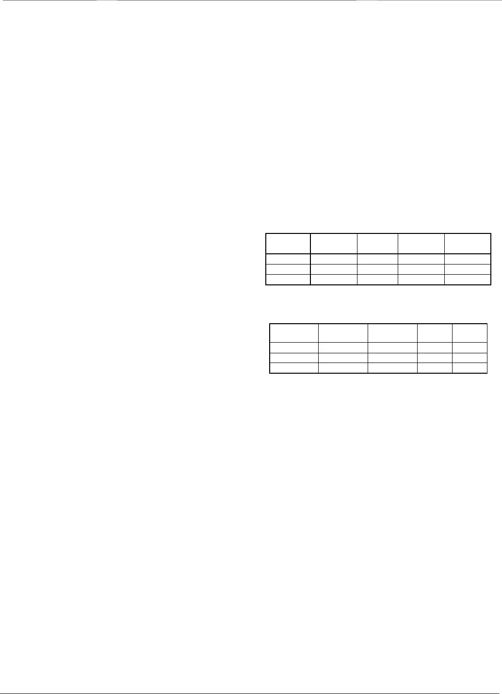
Table 2. Meter size and Flow Velocity (US unit)
Unit:gal/min
Meter size
(inch)
0.98 ft/s 3 ft/s 10 ft/s
32.8 ft/s
1/10” 0.02334 0.07115 0.2372
0.7781
1/6” 0.05975 0.1821 0.6071
1.992
1/4” 0.1344 0.4098 1.3660
4.482
About establishment environment
Do not store or install the flowmeter:
• Where there is direct sunlight.
• Where excessive vibration or mechanical shock
occurs.
• Where high temperature or high humidity
conditions exist.
• Where corrosive atmospheres exist.
• Places that can be submerged under water.
• Where there is a sloped floor. To put the flowmeter
temporarily on the floor, place it carefully with
something, such as a block, to support it so that the
flowmeter will not topple over.
In areas like the following, there may be the case that
infrared switches do not function correctly. (If these
are unavoidable, use an appropriate cover.)
(1) Where unit (operation panel) is exposed to direct
sunlight, reflection of light onto window pane and
diffused light reflection.
(2) Where smoke and steam may occur.
(3) Where exposed to direct snow, ice or mud.