


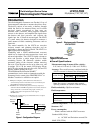

LF470/LF622
3
Communications output:
HART(std.)
Digital signal is superimposed on 4–20mAdc
current signal as follows:
Conforms to HART protocol
Load resistance: 240 to 750
Load capacitance: 0.25µF maximum
Load inductance: 4mH maximum
• PROFIBUS(opt.)
Protocol : PROFIBUS-PA
Baurate : 31.25kbps
Bus voltage : 9-30VDC
Consumption electric current of bus:less than 16mA
Manufacture Ident-No. : 093B
HEX
Standard Ident-No. : 9740
HEX
Slave address : 0-126 (Default address is 126)
Profile : Profile Ver.3.01 for Process Control
Devices
Function blocks : AI(Flow) 1 , Totalizer 1
• Modbus(opt.)
Physical layer : RS485
Protocol : Modbus
Mode : RTU
Baudrate : 4800, 9600, 19200bps
Data length : 8bit
Parity bit : None, Odd, Even
Stop bit : 1bit, 2bit
Error check : CRC-16
Max. station number : 32(with Master device)
Max. cable length : 1.2km (Note)
Note: This length is specification of 3 line
connection.
LCD display:
Full dot-matrix 128×128 dot LCD display
(back-light provided)
Parameter settings — Parameters can be set as
follows:
• IR Switches: Three key switches are provided to
set configuration parameters.
• Digital communication: The AF900 hand-held
terminal is needed to set parameters.
•Zero adjustment: Zero point adjustment can be
started by pressing the switch in the converter.
Damping: 0.5 to 60 seconds (selectable in one
second increments)
Zero and span calibration: Built-in calibration
signal source allows converter unit check.
Conditions when power fails: Parameter setting
values are stored in non-volatile memory and the
values will be restored when the power returns to
normal condition. The outputs and display will
remain as follows when power fails.
• Current output: 0mAdc
• Digital output: OFF
• LCD display: No display
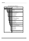
Power supply: One of the following can be selected:
• 100 to 240Vac, 50/60Hz (std.)
(allowable voltage 80 to 264Vac)
• 24Vdc (allowable voltage 18 to 36Vdc)
• 110Vdc (allowable voltage 90 to 130Vdc)
Surge protection: Arresters are installed in the
power supply, and current signal output circuit.
Case: Aluminum alloy (equivalent of IP 67)
Coating: Acrylic resin-baked coating, pearl-gray
colored
Cable connection ports:
Cable glands —
LF622 :Provided as standard
OD of cable 6mm
Material Nylon 66
G (PF) 1/2 male screws.
Note: When PROFIBUS or Modbus option is
specified , cable gland size is 6
8mm for signal cable, 11 13mm
for power cable
Applicable diameter — 11 to 13mm
(0.433 to 0.512 inch)
Vibration resistance:
No resonance to the following levels of vibration:
• 10 to 150Hz with acceleration of 9.8m/s
2
• Vibration of 30Hz with 29.4 m/s
2
in 4h in each
direction will not cause any defect to unit.
Note: Avoid using the flowmeter in an
environment with constant vibration.
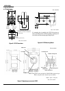
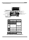
Converter LF622 dimensions :
See Figure 5 (for Separate type)
MTBF:220,000 hours at 25 deg.C (77 deg.F) based
on MIL-HDBK-217F