


7
6 F 2 S 0 7 3 8
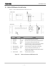
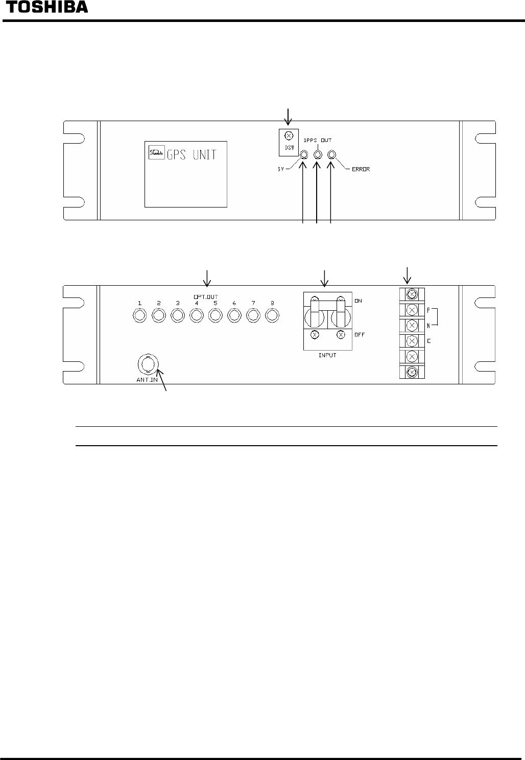
3.2 Outline of GPS Receiver Unit and Function
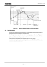
Figure 3.2.1 shows outline and functions of GPS receiver unit.
No. Device Indication Functions
①
Yellow LED 5 V Turns on when the power (5Vdc) is supplied.
②
Yellow LED 1PPS OUT Blinks when 1PPS signals are output synchronously with UTC.
③
Red LED ERROR Turns on when the internal crystal oscillator stops.
④
DIP switches DSW Set the GPS receiver unit settings. During operation, these DIP
switches are covered to prevent erroneous operations.
⑤
Signal output ports OPT.OUT Outputs time signals. The optical fibre is connected here.
⑥
Power supply switch INPUT Turns on or off the power of the GPS receiver unit.
⑦
Terminal block __ The 48V dc power is applied and the earth cable is connected.
P: 48Vdc, N: 0Vdc, E: earth
⑧
Antenna terminal ANT.IN The antenna cable is connected.
Figure 3.2.1 Outline and Functions of GPS Receiver Unit
⑤
⑥
⑦
⑧
②①③
④
REAR VIEW
FRONT VIEW
48V