


141-072011 - 201/203 Series Page 16 of 23
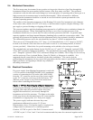
output is sent to the terminals on the back
and to the decoding circuitry in the display
which converts it to a 3-digit output.
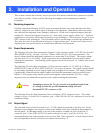
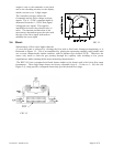
The controller circuitry utilizes the
Command and the Flow voltages as input
signals. The 0 - 5VDC command signal is
subtracted from the 0 - 5VDC flow signal
creating an error signal. This signal is
amplified and causes the solenoid valve to
move. The amount and direction of the
movement is dependent upon the value and
the sign of the error signal, and tends to
minimize the error signal.
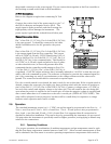
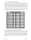
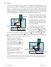
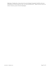
3.4. Shunt:
Measurement of flow rates higher than the
10 sccm full scale is achieved by dividing the flow with a fixed ratio shunting arrangement, as is
illustrated in Figure 3.3. This is accomplished by placing the measuring capillary tube parallel with
one or more dimensionally similar channels, called a laminar flow element (LFE). Therefore, the
sensor only needs to heat the gas passing through the capillary tube resulting in low power
requirements, while retaining all the mass measuring characteristics.
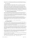
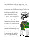
The HFC-203 uses corrugated and fused shunts similar to the shunts used in the lower flow range
instruments. These high range shunts are factory adjustable from 0 - 30 slm to 0 - 500 slm (see
Figure 3.4), using specific corrugated shunts that give the desired flow range.
FIG 3.2
FIG 3.3