


141-072011 - 201/203 Series Page 14 of 23
3) Step change the command voltage to 100%, and observe the flow through the controller. If the overshoot
is too large, remove the jumper. Reset the command voltage to 10%, and allow the controller to stabilize.
4) To prevent loss of the unused jumper, place it over one pin only on JP4/JP6.
2.6.9. Operating Temperature
For proper operation, the combination of ambient temperature and gas temperature must be such
that the Flowcontroller temperature remains between 0 and 50°C. Most accurate measurement of
flow will be obtained if the flow controller is re-zeroed at operating temperature, as temperature
shifts result in some zero offset.
2.7. Range Changing:
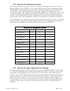
The range of the flow controller can be changed in the field if recalibration facilities are available.
The flow controller may require a different orifice, which can be purchased separately from the
factory. A listing of the orifices available and their flow rates can be found in Section 5.0. The
instructions to change the flow range can be found in Section 4.6.
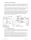
2.8. Valve-Override Control
The valve override control line provides a method to override the loop controller and open or close
the valve regardless of the flow or command signals. During normal operation this line must be
allowed to float freely. This will allow the loop control to open and close the valve as it requires. If
the valve override line is forced high (> +10 Volts) the valve will be forced full open. If the valve-
override line is forced negative (< 0 Volts) the valve will be forced closed.