


126B - PAGE 15
4.6 Printed Circuit Board4.6 Printed Circuit Board
4.6 Printed Circuit Board4.6 Printed Circuit Board
4.6 Printed Circuit Board
ReplacementReplacement
ReplacementReplacement
Replacement
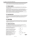
In the unlikely event that the PC board
fails, it is easily removed from the instru-
ment and replaced with a spare to minimize
instrument downtime. Replacement of the
PC board will require the instrument to be
recalibrated per Section 4.3.1.Unplug the
power cable from the top of the transducer.
Remove the two screws on the side of the
cover. Lift off the cover and unplug the
four-wire sensor plug noting the orientation
prior to removal.
Remove the screw that
holds the PC board to the sensor. Trouble-
shoot or replace as applicable. Installation is
the reverse of the above procedure.
Recalibrate if any components were
changed or if any potentiometers were
adjusted.
4.7 Sensor Replacement4.7 Sensor Replacement
4.7 Sensor Replacement4.7 Sensor Replacement
4.7 Sensor Replacement
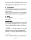
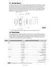
If the sensor fails or becomes plugged it can be
removed.
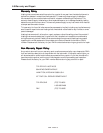
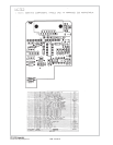
Remove the cover and the PC board per
Section 4.6 above. Remove the three bolts holding the sensor to the instrument base. Remove the
sensor from the base noting the two O-rings (Parker 2-005, V884-75) between the sensor and the base.
See Figure 4.3. If the sensor is plugged it can be cleaned by running a fine wire (approximately 0.008"
diameter) through the tube. If sensor needs replacement, obtain another from the factory and install it.
Ensure that O-rings are clean and intact. Install O-rings on seating surface, then carefully place sensor
over O-rings, and tighten down the three screws evenly. Replacement of sensor will require recalibration
per Section 4.3.1.
4.8 4.8
4.8 4.8
4.8
TT
TT
T
roubleshootingroubleshooting
roubleshootingroubleshooting
roubleshooting
SYMPTSYMPT
SYMPTSYMPT
SYMPT
OM:OM:
OM:OM:
OM: Output reads 40% of flow with no flow. Zero pot has no effect.
CACA
CACA
CA
USE:USE:
USE:USE:
USE: Power supply locked up or shorted out.
AA
AA
A
CTION:CTION:
CTION:CTION:
CTION: Turn off power supply for a few seconds, then turn back on. If this proves ineffective,
disconnect the unit from the power supply. If power supply display does not return to zero, then a
regulator chip in the power supply is probably burned out.
Check supply voltages and replace faulty regulator. If display
returns to zero after disconnecting the power supply from the
unit there is a short in the unit to ground. Check capacitors C11
& C13 first.
SYMPTOM:SYMPTOM:
SYMPTOM:SYMPTOM:
SYMPTOM: Output of unit is proportional to flow but
extremely small and not correctable by span pot.
CAUSE: CAUSE:
CAUSE: CAUSE:
CAUSE: Sensor is not being heated.
AA
AA
A
CTION:CTION:
CTION:CTION:
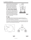
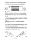
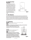
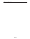
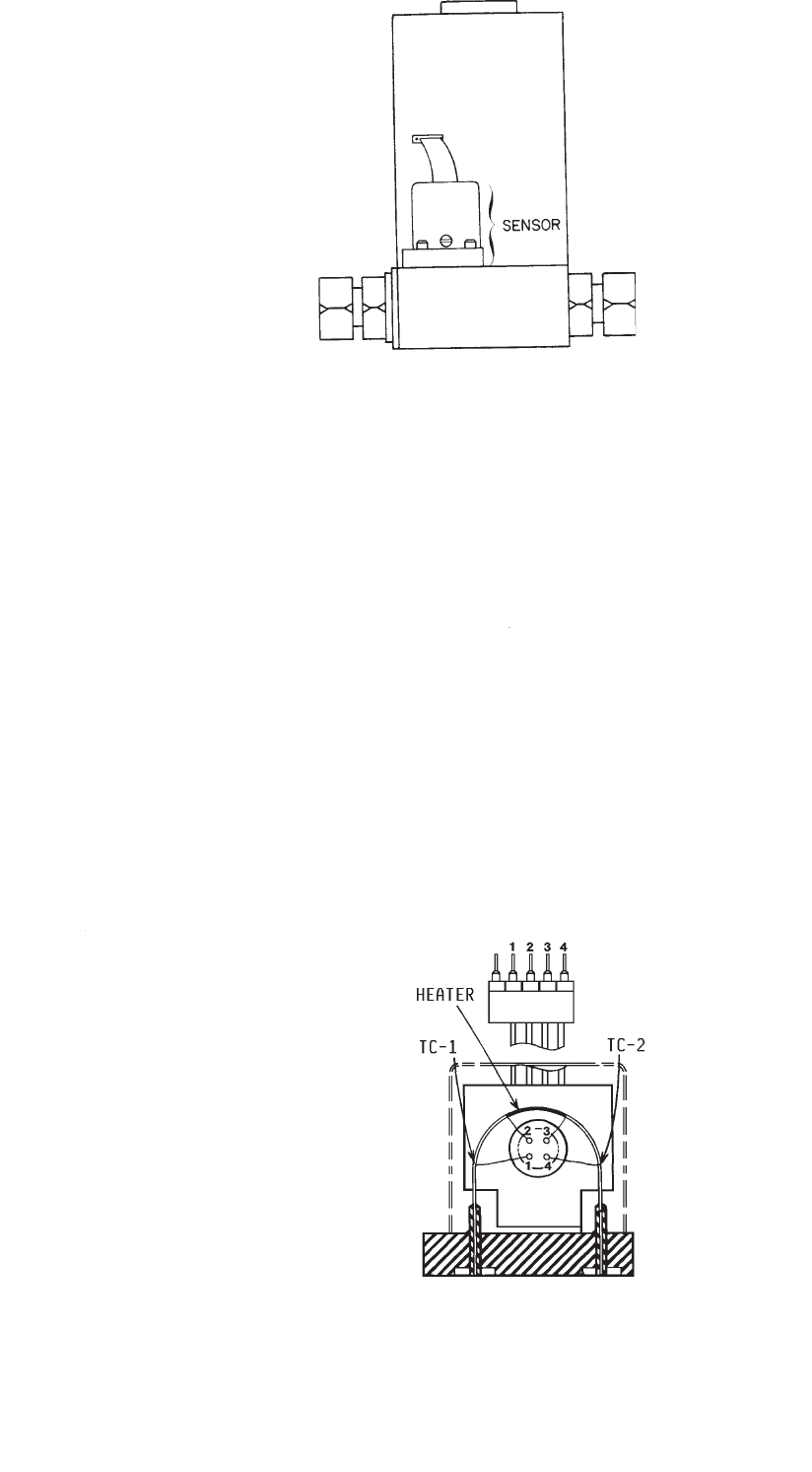
CTION: Unplug sensor from PC board (Fig. 4.3). Pins on sensor are
numbered from left to right. Begin counting with second pin from left (see Fig.
4.4). Check the resistance between pins 2 & 3 of the sensor. This will read between
2450 & 2550. Check the resistance between pins 1 & 4 of the sensor. This should
read approximately 2.3 ohms. If this reads open circuit, sensor was probably
plugged into PC board improperly and one of the thermocouples has been
destroyed. Replace sensor. Check the resistance between pin 2 and the base of the
sensor. This should be an open circuit. Repeat for pin 3 and the base. If resistance
readings are correct but sensor is not indicating flow, the sensor is probably plugged;
clean or replace as applicable.
Fig.4.3Fig.4.3
Fig.4.3Fig.4.3
Fig.4.3
Fig.4.4Fig.4.4
Fig.4.4Fig.4.4
Fig.4.4