126B - PAGE 10
For a constant power input, the differential thermocouple output is a function of the mass flow rate and
the heat capacity of the gas. Since the heat capacity of many gases is relatively constant over wide
ranges of temperature and pressure, the flowmeter may be calibrated directly in
mass units for those
gases. Changes in gas composition usually only require application of a simple multiplier to the air
calibration to account for the difference in heat capacity, and thus the flowmeter is capable of
measuring a wide variety of gases.
3.3 Electronics3.3 Electronics
3.3 Electronics3.3 Electronics
3.3 Electronics
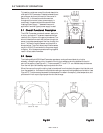
The Fast Response Model HFM uses a thermal flow sensor to measure flow through a capillary tube,
which is a fixed percentage of the total flow through the instrument. This sensor develops an output
signal proportional to flow which is approximately 0.8 mv full scale magnitude (see Figure 3.3). This
signal is amplified by the meter circuitry until it is 0-5.00 VDC. This 5 volt output is sent back to the
power supply and to the flowmeter circuitry, if applicable. At the power supply the 5 volt output is sent
to the terminals on the back and to the decoding circuitry in the display which converts it to a 3-1/2
digit output.
The Fast Response Model HFM uses additional electronics to achieve fast response characteristics by
amplifying the rate ofchange of the input signal, and adding it to the amplified input signal. The elec-
tronics are adjusted to provide response times of less than two seconds to 98% of a 0-100% step change
with less than 2% overshoot. The electronics also maintain the ouput signal above 5.00 VDC when the
flowrate exceeds the full scale flow of the flowmeter.
NONO
NONO
NO
TE:TE:
TE:TE:
TE:
The output signal will continue to increase above 5.00 VDC as the flow rate exceeds full scale flow,
however, the output above 5.00 VDC is non-linear and should not be used for flow measurement.
3.4 Shunt3.4 Shunt
3.4 Shunt3.4 Shunt
3.4 Shunt
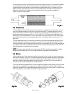
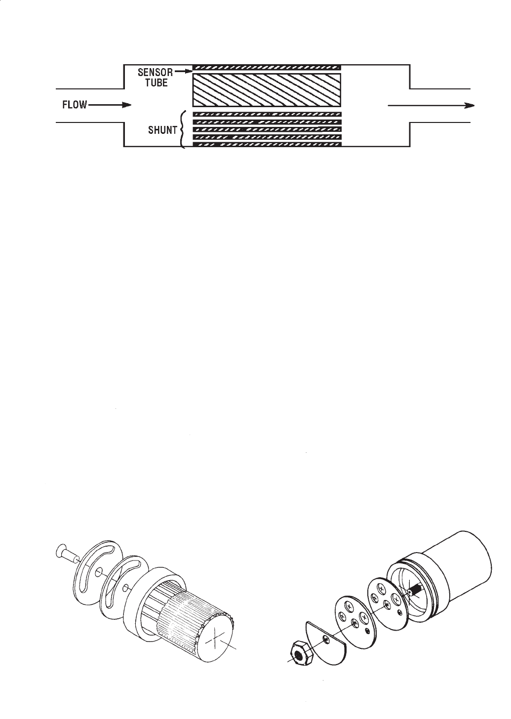
Higher measurement of flow rates is achieved by dividing the flow with a fixed ratio shunting arrange-
ment, as is illustrated in Figure 3.4. This is accomplished by placing the measuring capillary tube parallel
with one or more dimensionally similarchannels, called a laminar flow element (LFE). Therefore, the
sensor only needs to heat the gas passing through the capillary tube resulting in low power require-
ments, while retaining all the mass measuring characteristics.
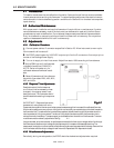
The HFM-229 has two possible shunts. The low range shunt consists of tubes inserted into a cylindrical
base. This shunt is adjustable for ranges from 0-10 sccm to 0-250 sccm (see Figure 3.5). The higher
range shunt consists of a corrugated stainless steel ribbon wound into a coil and fused. The higher range
shunt is adjustable from 0-0.3 slpm to 0-30 slpm ranges (Figure 3.6).
Fig.3.5Fig.3.5
Fig.3.5Fig.3.5
Fig.3.5
Fig.3.6Fig.3.6
Fig.3.6Fig.3.6
Fig.3.6
Fig.3.4Fig.3.4
Fig.3.4Fig.3.4
Fig.3.4


