


181-1216-14 Four-Cycle Engine • Vertical Crankshaft • Air-Cooled Page 9
III. Primer Bulb and Choke
In Temperatures above 40°F (5°C):
Follow instructions in Section A.I. See "I. Primer Bulb Only"
instructions on page 7. See Table 3 on page 7.
In Temperatures below 40°F (5°C):
1. To avoid carbon monoxide poisoning, be sure engine is
outdoors in a well-ventilated area.
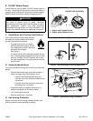
2. Move engine throttle control to “CHOKE” or “START”
position, if present (see equipment manufacturer’s
instructions). See Figures 17, 18 and 19.
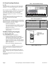
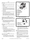
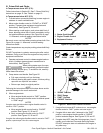
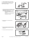
3. When starting a cold engine, press primer bulb firmly 3
times, allowing primer bulb to return completely to orig-
inal position between pushes. See Figures 15 and 20
starting on page 8. Afterward, continue reading instruc-
tions below.
NOTES
Be sure to cover vent hole when pressing primer bulb.
See Figure 20.
Cooler temperatures may require pushing primer bulb firmly
5 times.
DO NOT use primer to restart a warm engine after a short
shutdown. Doing so will flood the engine and may result in
equipment malfunction.
4. Operate equipment control to release engine brake or
clutch, if present (see equipment manufacturer’s
instructions). See Figure 17.
NOTE
DO NOT operate an electric starter for more than 5 seconds
each attempt.
5. Push starter button or turn ignition switch key to start
engine.
6. When engine starts:
a. Release starter button or ignition switch key.
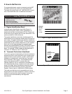
b. Move engine throttle control to “FAST” position. See
Figures 17, 18 and 19.
c. Next, move engine throttle control to desired speed
in “RUN” range.
NOTES
If engine starts but falters when engine throttle control is
moved to “FAST” position:
a. Move engine throttle control back to “CHOKE”
position. See Figures 17, 18 and 19.
b. Next, move engine throttle control to “FAST”
position. See Figures 17, 18 and 19.
If engine dies after engine throttle control is moved to
“FAST” position, repeat steps 2 thru 6 to restart engine.
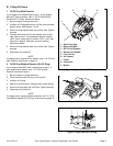
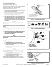
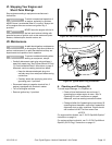
Figure 17. Typical Engine Controls
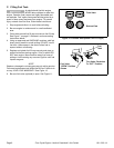
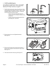
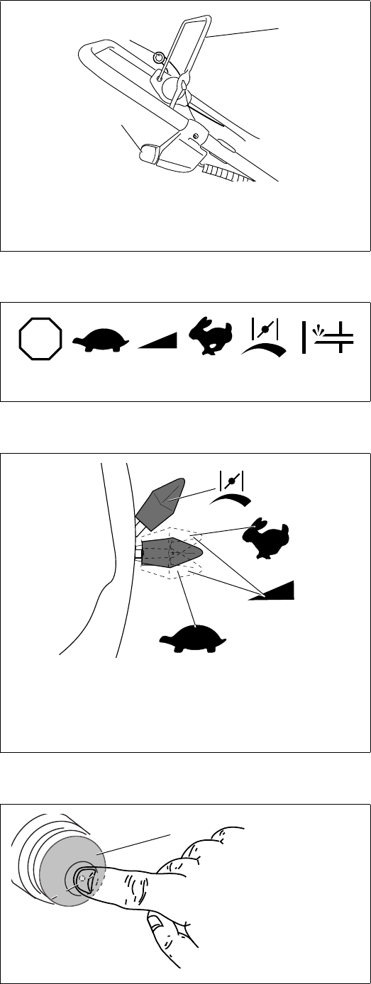
Figure 18. Typical Engine Symbols
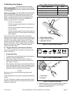
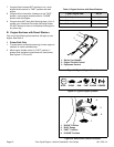
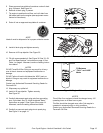
Figure 19. Start/Choke Control Positions
Figure 20. Pressing Primer Bulb
1. Electric Start Switch
2. Engine Throttle Control
3. Equipment Control
1
3
2
STOP
STOP SLOW RUN FAST CHOKE PRIMER
1. “SLOW” Position
2. “RUN” Range
3. “FAST” Position
4. “CHOKE” Position
4
3
2
1
1. Primer Bulb
2. Vent Hole
1
2