3
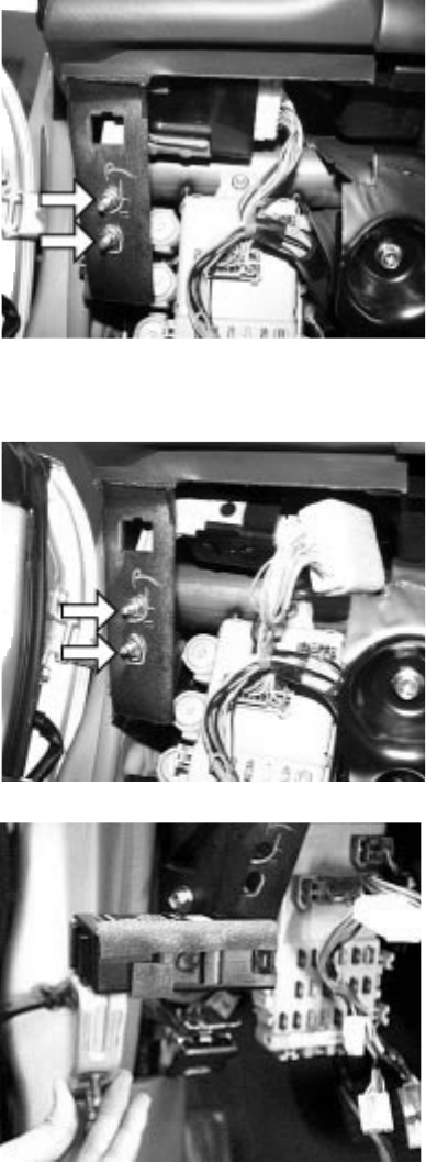
Figure 3
4. Insert the 16-pin (white housing) connector into the key-
less entry module.
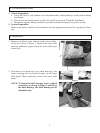
5. Install the keyless entry module to the location previ-
ously used by the door lock timer module and secure it
in place with two M6 nuts removed in Step 3. Refer to
Figure 4 which shows the installed keyless entry mo-
dule.
3. Remove two M6 nuts, indicated by arrow in Figure 3,
securing both the door lock timer module. Retain nuts
for installation of keyless entry module. Disconnect the
door lock timer harness from the module and discard the
module. Disconnect 6-pin to 16-pin extension harness
from the 16-pin (white housing) connector. Discard the
extension harness.
Figure 4
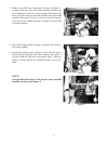
NOTE:
The installed direction of the keyless entry module
should be as shown in Figure 5.
Figure 5


