22
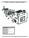
Assemble the bushing and blower hub with the bolts
inserted (but not tightened) through the drilled holes in the
blower hub and into the tapped holes in the bushing.
With the key in the shaft, slide assembly into position
on the shaft and tighten the setscrew over the key (if
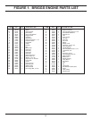
equipped). Tighten the 3 capscrews (14, fi g.1) alternately
and evenly to 60-inch pounds. There should be a gap be-
tween the face of the bushing and hub.
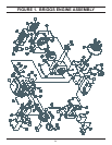
BLOWER WHEEL REMOVAL
(see fi gure 1)
1. To remove the blower wheel, fi rst follow steps 2 through
5 of the Hydraulic Tank Removal.
Note:
Do not remove the hose at the bottom of the hydraulic
tank (11, fi g. 3).
It is not necessary to drain the hydraulic tank when only
removing the blower wheel.
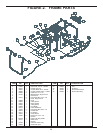
2. Remove the front grille (22, fi g. 1) by removing the 4 but-
ton-head screws (19, fi g. 1).
3. Remove the 4 hex fl ange bolts (28, fi g. 1) that hold the
blower wheel on.
4. The blower wheel can now be removed by lifting it out
through the top opening of the blower housing.
5. Replace the blower wheel by reversing the above proce-
dures.
CHOKE CABLE ASSEMBLY REMOVAL
(see fi gure 1 & 2)
1. The choke cable assembly can be removed by removing
1 screw (57, fi g.1 Briggs).
2. Disconnect cable from carburetor linkage.
3. Remove hex nut from back of dash panel and pull choke
cable assembly out through the hole in dash panel
4. Reinstall in reverse order.
CONTROLLER REMOVAL (see fi gure 1)
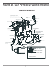
Refer to the wiring diagram in this manual for the correct
connections.
SERVICE
1. Unplug the 2 12-pin Deutsch connectors attached to the
controller.
2. Remove the 2 hex washer head screws (56, fi g.1).
Note:
The controller is software programmable and has no
manual adjustments. The controller must be loaded with
the proper program (Briggs) to operate the unit correctly.
Without the controller programmed, the power unit will
not start. Refer to the "Programmable Controller" section
in this manual.
FRAME ASSY & RELATED
COMPONENTS
FUEL TANK (see fi gure 1)
IMPORTANT
Never change any wiring connections. If
wires are not connected correctly, compo-
nenets could be damaged.
If the fuel tank contains fuel, take extreme precautions to
remove the fuel into approved containers. Do not attempt
to service the fuel tank in unventilated areas or in areas
containing electric or natural gas appliances which may
start-up unexpectantly or in shop areas where grinding or
welding is present, all of which can ignite the fuel vapors.
1. Remove both battery connections and remove the bat-
tery.
2. Remove the fuel line from the tank by pulling it off the
fuel pump end.
3. Remove the 4 hex fl ange bolts (30, fi g. 1) under the fuel
tank that hold it to the frame base weldment.
4. The tank can now be removed.
Note:
The positive and negative battery cables must be fed
through the fuel tank as it is removed.
5. Thoroughly clean the tank and replace the fuel fi lter.
6. Use the reverse procedure to reinstall the fuel tank.


