


2
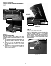
STEP 3
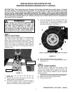
INSTALL FRONT TIRES
The front bumper can be used to lift the front of the
machine. Block the machine to prevent it from falling.
NOTE: The front tires are directional. Install with valve
stems out and with the points of the chevron treads
pointing forward.
1. Loosen only, two lug nuts at left and right front
wheel hubs.
2. Remove the four bolts securing the left and right
support plates to the crate bottom.
3. Lift front of machine only high enough to install front
tires. Block machine securely to prevent it from
falling. Remove support plates.
4. REMOVE OPERATOR PROTECTIVE STRUCTURE
FROM CRATE BOTTOM AT THIS TIME.
5. Install left and right front tires and secure each with
5 lug nuts.
6. Remove blocks and lower machine.
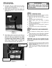
7. Torque lug nuts to 75 ft-lb using sequence shown.
See Figure 1.2.
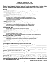
STEP 4
ADJUST TIRE PRESSURE
IMPORTANT! Correct tire inflation pressure is critical to
the proper handling and braking of the machine.
1. Using a low-pressure tire gauge, check tire
pressure.
2. Adjust tire pressure to 15 psi.
WARNING
Operator Protective Structure and Seat Belts must
be installed and all mounting hardware tightened
securely before starting or operating machine.
STEP 5
INSTALL SEAT BELTS
Mounting of seat belts is very important. Assemble
carefully using the sequence shown. The seat belt with
the latch plate is typically attached at the outside
mounting hole. The seat belt with the buckle is attached
at the inside or middle mounting hole. Tighten hardware
to a snug rotating fit as described below.
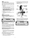
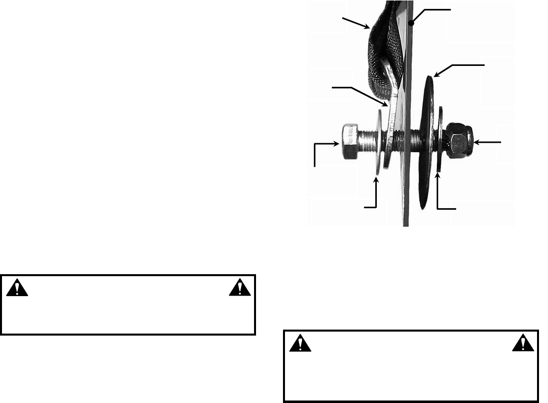
IMPORTANT! The large 2 1/2” diameter flat washers
must be installed on the inside surface of the seat
support structure. See Figure 1.3.
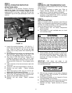
1. Remove the top two bolts from the fuel tank straps
and slide tank out. This will allow clearance to
install the bolt used to mount the right seat belt.
See Figure 1.4.
NOTE: tank straps remain loose until STEP 6, Operator
Protective Structure installation has been completed.
2. Locate seat belts and hardware bag.
3. Place (1) 1/2” x 1 1/4“ diameter flat washer on (1)
7/16-20 x 2” bolt. Insert bolt with washer into seat
belt mounting plate. See Figure 1.3.
4. Insert bolt into hole in seat support. Place large
2 1/2” diameter flat washer over bolt against inside
surface of seat support.
5. Place (1) 1/2” x 1 1/4” flat washer on bolt. Install (1)
7/16-20 top lock nut.
FIGURE 1.3
6. Tighten nut to a snug rotating fit. When properly
tightened the mounting bracket should be able to
rotate with some resistance to align properly with
seat position and size of operator, but not rattle.
7. Repeat for remaining three belts.
WARNING
Safe operation of machine limits total occupants to
(2), one operator and one passenger. Seat belts
must be securely latched and adjusted to a snug fit
before starting or operating the machine.
REPRESENTING
SEAT SUPPORT
STRUCTURE
SEAT
BELT
MOUNT
PLATE
7/16
-
20X2”
HEX BOLT
1/2”X1
-
1/4”
FLAT WASHER
1/2”X1
-
1/4”
FLAT WASHER
7/16
-
20
NYLOC
NUT
2
-
1/2”
DIAMETER
FLAT
WASHER