


Si824xClassD-KIT
6 Rev. 0.2
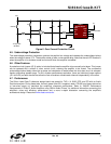
5. Si8241-Based Class D Amplifier Connection Description
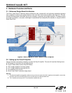
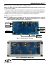
The Si8241-based Class D Amplifier has two Si8241 ISOdrivers and two Si8410 digital isolators installed. Refer to
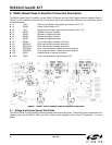
Figure 7 for the locations of the various I/O connectors and major components. Relevant user connection points
are detailed below.
J1 +50 V Positive Input Power: Input power connection +50 V, 3 A.
J2 PGND Power Ground Return, 0 V.
J3 –50 V Negative Input Power: Input power connection –50 V, 3 A.
J4 SPKA+ Speaker A positive terminal
J5 SPKA– Speaker A negative terminal
J6 SPKB+ Speaker B positive terminal
J7 SPKB– Speaker B negative terminal
J8 VBIAS ±12 V Bias supply connector (500 mA)
J9 AUDIO A RCA input female connector channel A
J10 AUDTIO B RCA input female connector channel B
JP1 OCPDISA Over current protection disable channel A channel
JP2 OCPDISB Over current protection disable channel B channel
JP3 MUTE Amplifier Mute or manual shut down
LED1 FAULT Over current protection fault indicator LED
Figure 7. Si8241 Si8241-Based Class D Amplifier Silkscreen
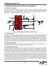
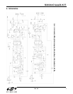
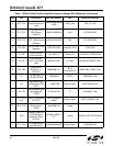
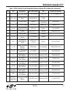
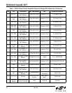
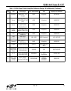
5.1. Voltage and Current Sense Test Points
The Si824x Class D Audio Amplifier reference design has several test points. These test points correspond to the
respective pins on the Si8241, Si8410 as well as other useful inspection points. See “6. Schematics” for more
details.