


Si824xClassD-KIT
4 Rev. 0.2
4. Additional Features and Architectural Considerations
4.1. Gate Drive Structure
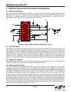
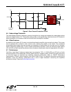
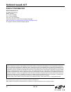
Figure 5 illustrates the ease with which the Si8241 can drive a two-state, half-bridge class D amplifier. The boot
supply tied to D1 must be 12 V higher than the –50 V reference (–38 V) so that the MOSFETs each have a 12 V
drive signal. The closed loop gain of the Silicon Labs Class D reference design is implemented such that
approximately 1 Vpp input will yield full output power into an 8 load.
Figure 5. Si8241 Audio Gate Driver Gate Drive Circuit
4.2. Self Oscillation
The amplifier is self-oscillating, enabling its signal-to-noise ratio to far exceed that of a clock driven system. The
main mechanism for this is the delta-sigma effect of shifting in-band noise to a much higher out-of-band frequency.
The amplifier is a basic, phase-shift type, which has significant advantages over an amplifier running as a
hysteretic oscillator. There is a pole in the forward path G(s) and a pole in the feedback path H(s). The 180 ° phase
shift, coupled with the transport delay, yields an oscillation frequency of nearly 500 kHz. The frequency of
oscillation is set by capacitors in each audio channel where reducing capacitance value increases oscillation
frequency. Tight tolerance capacitors are used to keep the channel frequencies as close to each other as possible.
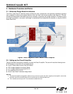
4.3. Heat Sink L-Bracket
The amplifier design includes an L-bracket to sink excess heat from the power transistors. At full power, the L-
bracket's temperature should increase to no higher than 80 degrees Celsius.
4.4. Overcurrent Protection
The Silicon Labs Class D reference design has an overcurrent protection circuit consisting of a low-power
comparator floating off the upper and lower bus voltages. The upper rail circuit is shown in Figure 6 and is
duplicated on the lower rail. It monitors the current flowing through the 0.005 resistor (RSENSE). Zener diode D1
and resistor R4 supply power to the comparator and the Silicon Labs Si8410 digital isolator. The Si8410 performs
the necessary level shifting to interface to the shutdown circuitry. The circuit is set to trip at roughly a 20 A fault,
usually caused by a short-circuit across the speaker terminals or a large overdrive signal at the audio inputs. Note
the upper and lower overcurrent circuits are ORed together through a pair of diodes and sent to the reset control
circuit. The normally low Si8410 A1 input is driven high upon detection of an overcurrent condition and asserts the
SHUTDOWN signal, forcing the reset controller to assert a reset signal, momentarily halting amplifier operation.
The reset control circuit attempts restart after one second, and, if the fault is still present, again cycles reset in
“hiccup” mode with a frequency of one second. This process continues until the fault is removed. Overcurrent
protection can be removed by uninstalling JP1 and JP2.
Si8241
ISOdriver
-38V
PWM
NC
VDDI
GNDI
DISABLE
DT
NC
VDDI
VDDA
VOA
GNDA
NC
NC
VDDB
VOB
GNDB
-50V
+50V
C1
C3
PWM
+5V
C2
SHDN_HI
R3
C4
D1
R1
R2
-38V