Series 730 Instruction Manual
6 IM-73-E
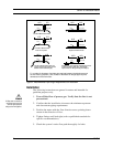
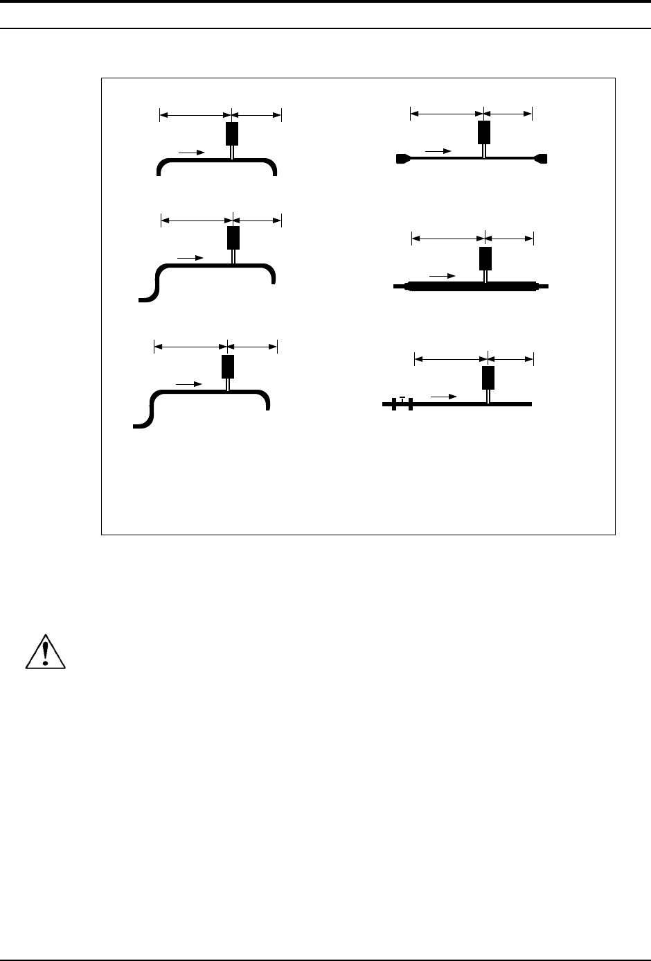
Flow meter
10 D 5 D
One 90° elbow before meter
Flow meter
15 D 5 D
Two 90° elbows before
meter in one plane
Flow meter
25 D 10 D
Two 90° elbows before meter out
of plane (if three 90° bends present,
double recommended length)
Flow meter
10 D 5 D
Reduction before meter
Flow meter
20 D 5 D
Expansion before meter
Regulator or valve partially closed before meter
(If valve is always wide open, base length
requirements on fitting directly preceding it)
Flow meter
25 D 10 D
D = number of diameters of straight pipe required between the disturbance and
the flow meter (upstream); and, number of diameters of straight pipe required
downstream of the flow meter
Flow
Flow
Flow
Flow
Flow
Flow
Figure 2. Recommended Pipe Length Requirements for Installation
Installation
The following instructions are general in nature and intended for
guideline purposes only.
1. Turn off the flow of process gas. Verify that the line is not
pressurized.
2. Confirm that the installation site meets the minimum upstream
and downstream piping requirements.
3. Position the meter with the flow direction arrow pointing down-
stream in the direction of flow.
4. Tighten fittings until leak tight (refer to published standards for
specific recommendation).
5. Check the system’s entire flow path thoroughly for leaks.
Caution!
All flow meter connections
and fittings must have the
same or higher pressure
rating as the main pipeline.


