


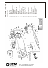
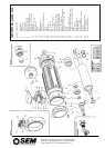

REMOVAL OF
AC TACHO
Instructions common to
HD 55, HD 70, HD 92, HR 92
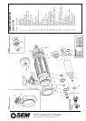
Extreme care to be taken during the removal and re-
assembly of the Tacho. When stripping Tacho Motor, Tacho
parts must be removed first.
1. Disconnect leads at feedback connector
2. Undo screws holding PCB board and lift off
3. Undo screws holding Tacho stator in N.D.E. cover and lift out.
4. With suitable extractor, pull out the Tacho rotor, taking care not to
damage these components.
5. Continue with dismantling of the motor.
Re-assembly
6. Replace the stator, fit tacho rotor and PCB in the correct position.
The screws that clamp the stator to PCB must not be
over tightened – this causes the PCB to distort. Use a suitable
Loctite or similar screw lock adhesive, to prevent screws from
loosening.
7. Refit rotor noting original position and using a power supply to
position motor rotor as during removal. Lock rotor with clamp nut
and tighten using correct torque. (See torque tables).
8. Refit stator, rotor and PCB Assembly. Refit screw aligning position
of PCB relative to the end housing. Reset tacho using appropriate
electrical device.
REMOVAL OF DC TACHO
(1) Remove cable from processing PCB
(2) Remove processing PCB by pulling it off the 3 connectors which
support it. Then proceed as AC tacho.
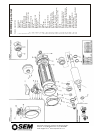
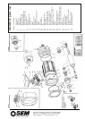
REMOVAL OF
AC TACHO
Instructions common to
HD 92, HR 92, HD 115, HR 115 HD 142,
HR 142, BMR 190/HD 190
Extreme care to be taken during the removal and re-
assembly of the Tacho.
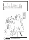
1. Mark the relationship of PCB to the end housing (11). Insert a strip
or tube of non-magnetic material (e.g. card or plastic) in the air gap
between stator and rotor to prevent demagnetising the rotor and
damaging the windings. (ROTOR MUST BE PROTECTED FROM
CONTACT WITH ANY FERROUS METAL TO PREVENT
DEMAGNETISATION).
2. Unplug cables from the PCB and remove the 3 screws holding the
PCD to the end housing. Carefully remove the PCB and stator
assembly.
3. To mark the position of rotor, connect a D.C. power supply to motor
terminals U(+ve) and V(-ve), adjust the voltage to give a current
between 25% and 100% of the motor rated current. The rotor will
move to a preferred position. If motor has a brake, it must be
released to allow this to happen. Then mark position of tacho rotor
relative to the end housing.
4. WE STRONGLY RECOMMEND THAT CUSTOMERS DO NOT
REMOVE THE STATOR FROM THE PCB. However, if the Stator
has to be removed, proceed as follows: To remove the stator from
the PCB – mark position of stator relative to PCB, unscrew the
screws holding the PCB to stator and separate.
NOTE: IT IS RECOMMENDED THAT IF ANY PARTS OF THE
TACHO ARE TO BE REPLACED, THE COMPLETE MOTOR BE
RETURNED TO SEM FOR IN-HOUSE REPAIR.
Re-assembly
5. Replace the stator on PCB (if it was removed) in the correct
position. The screws that clamp the stator to PCB must not be over
tightened – this causes the PCB to distort. Use a suitable Loctite or
similar screw lock adhesive, to prevent screws from loosening.
6. Refit rotor noting original position and using a power supply (as
para. 3) to position motor rotor as during removal. Lock rotor with
clamp nut and tighten using correct torque. (See torque tables).
7. Refit stator and PCB assembly protecting rotor from contact with
stator as during removal. Refit screw aligning position of PCB
relative to the end housing.
REMOVAL OF DC TACHO
(1 ) Remove cable from processing PCB
(2) Remove processing PCB by pulling it off the 3 connectors which
support it. Then proceed as AC tacho.
SEM Limited, Faraday Way,
Orpington, Kent BR5 3QT England
Telephone: +44 (0) 1689 884700
Fax: +44 (0) 1689 884884
E-mail: info@sem.co.uk
Internet: http://www.sem.co.uk
UL VERSIONS
AVAILABLE
WARNING
Servomotors contain magnetic material which will attract metal particles. Care should be
taken when dismantling motors to avoid this.
All D.C. servomotors manufactured by SEM contain magnets which are air stable and can
be dismantled without demagnetisation