


BMR/HD/HR190
servicing instructions
1 GENERAL
1.1 Before starting work on the motor, these servicing instructions should be
read and fully understood.
1.2 Servicing of SEM motors must be done only by suitably trained and qualified
personnel, and only after such motors have been electrically isolated and
removed from their mechanical drives.
1.3 The jaws of any vice or clamp must be suitably protected when used to grip
any part of the motor.
1.4 When separating the motor end covers from the motor body, care must be
taken to avoid damage to their mating surfaces.
1.5 NOTE. There are strong magnetic forces between the stator and the
rotor of all SEM servomotors. Fingers should be kept clear of the gaps
between the stator and end covers during assembly and disassembly
of the rotor.
1.6 Dismantled components awaiting reassembly, should be kept in a safe, clean
and dry location.
Various types of encoder are used, involving different procedures for
dismantling, reassembly, connection, setting up and testing. Contact
SEM with regard to relevant servicing procedures for the particular type
of encoder involved.
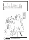
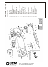
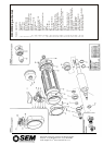
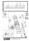
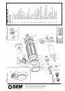
2 MARKING
2.1 The following relationships must be marked with a marker pen or other
suitable method before dismantling.
2.2 Drive end (DE) cover (A) to motor body (B).
2.3 Non-drive end cover (D) to motor body (C).
2.4 Enclosing Cover (17) to non-drive end (NDE) cover (11).
2.5 Prior to resolver dismantling, mark outside end faces of resolver stator (4)
and resolver rotor (3)
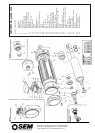
3 DISMANTLING THE MOTOR
3.1 Remove M5 socket screws from NDE enclosing cover (17), remove the end
cover and the O Ring.
3.2 Grip the drive end of the rotor shaft (1) in a suitably protected vice and
loosen the nut (2). Leave this nut finger tight until the resolver is required to
be removed. (Note that a special tool is required, available from SEM).
Remove the unit from the vice at this point.
3.3 Disconnection sequence, (MS Connectors option). Remove 8 fixing
screws and pull M.S. plugs (29 & 30)
clear of non drive end housing
sufficiently to allow access
to wires for unsoldering of existing connectors.
When the wires are unsoldered, the M.S. connectors can be removed. (It is
important to note all connections prior to unsoldering).
3.4 Disconnection sequence, (Terminal Box assembly option). Remove
terminal box screws (27)
lid, (21) and gasket (28). Unsolder all connections
from M.S. Connector (30) and release 3 motor leads and 2 brake leads from
terminal block (23). To remove the terminal box (20) from the non drive end
housing, remove screw and nut (25 & 26).
3.5 Removal of Resolver. Important. At all stages of removal and reassembly,
the resolver unit must be handled with care. (See Para 14). Unscrew (7 & 8)
and release resolver body (4) complete. Remove nut (2), noting that at this
point the resolver rotor (3) is free, and will drop out of the resolver body
unless held in place by hand. Remove the resolver and store in a safe place
until re-assembly.
3.6 Removal of Drive End Cover, (Non Brake models). (Do not lever between
body and end covers under any circumstance). Remove 4, M8 socket screws
(36). Do not attempt to separate the N.D.E. housing from the motor body at
this stage. Remove 4 screws (35) and separate the drive end cover from the
motor body (10) and rotor shaft (1). Remove and discard the oil seal (19) and
the O-ring (13) (note that the oil seal must be pressed out using a suitable
tool. The rotor assembly is now free to be removed, via the non-drive end,
but it is still attached to the N.D.E. cover by N.D.E. bearing (6).
3.7 Removal of N.D.E. Housing. TAKE CARE! The rotor itself is covered by a
protective tape, and before any attempt is made at further withdrawal, the
rotor must be properly supported and eased through the motor body so that
the tape is not damaged in any way. This is most important. To remove rotor
from N.D.E. cover, remove circlips (14) from N.D.E. cover to release N.D.E.
bearing (6). Support the N.D.E. cover and rotor assembly in such a way as to
allow the rotor to be gently tapped or pushed out of the housing. (Only use a
hide mallet if tapping out is necessary).
3.8 Removal of D.E. Cover (Brake Models) Remove 6 screws which hold
brake assembly to D.E. housing, then follow instructions as for non-brake
model, (Para.7). When drive end cover is removed, the brake assembly (38)
and bearing (15) are left on the rotor shaft (1). After removing circlip (41) the
bearing itself can only be removed by use of a suitable tool. This will leave
the brake assembly free to be removed from the rotor shaft after
disconnection of the relevant ‘spade’ connectors. Then follow instructions as
applicable to nonbrake motor (section 3.7).
4 RE-ASSEMBLY OF MOTOR
4.1 Note: New circlips, bearings, oil seals and O-ring must be fitted on re-
assembly as standard procedure. Also ensure that all marks made under
section 2 are in alignment as applicable. Fit bearing (6) into N.D.E. housing.
Fit D.E. Bearing (15) onto rotor (1). Supporting inner race of N.D.E. bearing,
press rotor assembly back into N.D.E. housing, fit circlip (40). Fit new O-ring
(13).
4.2 Carefully re-insert assembled rotor and N.D.E. housing through the motor
body at the same time feeding connection wires through the crescent shape
hole in the N.D.E. housing, taking care not to trap wires or to damage the
protective tape on the rotor when completing this assembly. Tighten screws,
using correct torque (see torque table). Refit brake when fitted and fit bearing
(15) (reconnect ‘spade’ connectors). Refit drive end housing (12) with wave
washer (16) and O-ring (13) in position. Refit screws and tighten to correct
torque (see torque table). Fit oil seal (19).
4.3 Refit Resolver. Slide Resolver body into non drive end of rotor shaft and
screw into N.D. E. housing using screw (7) and clamps (8). Refit resolver
rotor (3), refit nut (2) and tighten to correct torque (see torque table), gripping
drive end of rotor shaft in a suitably protected vice (as section 3.2). Re-
assemble M.S. connectors or terminal box assembly as applicable, in
reverse sequence to sections 3.3 & 3.4.
5 RESETTING THE RESOLVER.
5.1 This only applies to a standard resolver supplied by SEM with the standard
setting. For any other resolver, refer to the drive manufacturer.
5.2 For these procedures it is necessary to make connections and links to
feedback connector pins. To avoid damage to these pins, it is advisable to
make such connections and links via a suitable separate test socket which
mates with the feedback connector multi-pin plug (30) and which has short
leads connected to its sockets. Alternatively appropriate pins can be made
available for connections and links by withdrawing them from plug (30) as in
Section 3.3 and 3.4 “Disconnection”.
5.3 If a brake is used, it must be temporarily held off during this operation by
applying a 24V dc supply across the brake terminals.
5.4 Undo 4 screws (37) and pull back the enclosing cover (17) to give access to
the resolver. With the above test plug connected to the feedback connector,
link pins R1 to S3 & pins R2 to S2. Connect a signal generator (approx 5V
6kHz) between pins R1 and R2. Connect an AC voltmeter between pins S1
and R2.
5.5 At the power connector, link motor phase pins V and W and then connect a
low voltage dc supply to motor phases at power connector pins U (+ve) and
V+W (-ve). Adjust this voltage to give between 25% and 100% of motor rated
current thereby causing the motor to turn to a preferred position.
5.6 Slacken the 3 screws (7) holding the resolver stator and then rotate it until
the voltmeter gives a maximum reading. Reconnect the AC voltmeter to pins
S4 and R2. Make a small final adjustment of the resolver stator to get a
minimum reading. Retighten the screws, disconnect the test socket, the
supplies, the voltmeter and links, let the brake (if used) be re-applied.
5.7 Attach the protective shield (if fitted) to the resolver and fix the enclosing
cover (17) to the NDE cover in accordance with marks made in operation
2.4.
6 ELECTRICAL TESTS NECESSARY
BEFORE CONNECTING MOTOR TO
AMPLIFIER.
6.1 Measure motor stator winding resistances U-V, V-W, W-U. These must be
equal to within 3%.
6.2 Check dielectric strength by flash test at 1000 Vac from:
a Phase U (power connector pin) U to motor body.
b Phase U to thermal sensor (feedback connector pins Thermal Sensor +
and Thermal Sensor -).
c Phase U to brake connections (power connector pins B+ & B-).
If flash test is not possible then check that insulation resistance is greater
than 1megaohm.
6.3 Check dielectric strength by flash test at 500Vac or with a 500Vdc supply
from motor body to:
d Brake connections (power connector pins B+ and B-)
e Thermal sensor (feedback connector pins Thermal Sensor + and
Thermal Sensor -)
6.4 Resolver (feedback connector pins R2 and S1.f flash test is not possible then
check that insulation resistance is greater than 1megaohm.
SEM Limited, Faraday Way, Orpington, Kent BR5 3QT England
Telephone: +44 (0)1689 884700
●
Fax: +44 (0) 1689 884884
E-mail: info@sem.co.uk
●
Internet http://www.sem.co.uk