


Page 16 - Astra 7E7
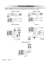
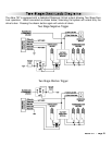
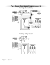
Starter Defeat Connectors
Using a volt/ohm meter locate the starter wire (normally a heavier gauge wire) at the ignition switch. This
wire will show +12V only during cranking. When this wire is cut the vehicle will be unable to start.
Locate the BROWN starter disable wire included with the wiring harness and cut in half. After cutting the
vehicle’s Starter circuit wire, connect one half to the cut side of the vehicle’s starter wire coming from the
key switch. Connect the other BROWN wire to the other half of the vehicle’s starter circuit cut wire going
to the starter. Plug the female connectors on the BROWN wires to the .250 male spade lugs on the module.
With the BROWN wires connected to the module, the vehicle should be able to start.
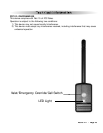
2-Pin Red Connector: Plug-in connector port for LED. Mount the LED in an area where it may be easily
seen from either side of the vehicle.
2-Pin Blue Connector: Plug-in connector port for valet switch. Mount the valet switch in an area that is
easily accessible from the driver’s position.
4-Pin White Connector : Plug-in connector port for dual stage shock sensor.
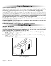
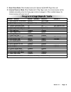
Jumper Selection
Carefully separate the top and bottom halves of the main unit case. Once the cover is removed, the parking
light polarity jumper will be visible next to the parking light relay. Set the jumper for the correct polarity
output as described below, then reassemble the main unit case.
Parking Light Output. Selects the polarity (+/-) for the output of the on-board Parking Light relay.
Right Pin & Center Pin = positive
Left Pin & Center Pin = negative
Dome Light Output. Selects the polarity (+/-) for the output of the on-board Illuminated Entry relay.
Right Pin & Center Pin = positive
Left Pin & Center Pin = negative
Jumper
Settings
default setting shown
Plug
in
Connectors