


Page 8 - Astra 100RS
System
Wiring
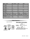
Starter Relay Module Harness
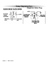
Pin 1 ORANGE WIRE: Accessory Output for heater/air conditioner- Connect to the vehicles wire that
shows +12v in the Run and On position but shows no voltage when cranked.
Pin 2 YELLOW WIRE: Ignition 1 output- Connect to the Vehicle’s wire that has +12v constant in the On
position and when cranked.
Pin 3 VIOLET WIRE: Starter Output - Connect to the vehicle’s wire that shows +12v when cranked.
pin 4 BROWN WIRE: Ignition 2 output- Connect to the Vehicle’s wire that has +12v constant in the On
position and when cranked.
pin 5 RED WIRE: +12V Power Input- Connect to a (25A) +12v constant Battery source.
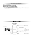
16-Pin Main Harness
Pin 1 BLUE WIRE - 1 pulse remote start (-) input. Connect to auxiliary output from aftermarket alarm.
Pin 2 BLACK/GRAY WIRE: Tach Input. (required for all manual transmission installations) Connect
to the vehicle’s tach wire or a fuel injector wire if the tachless mode does not provide satisfactory
operation.
Pin 3 WHITE/RED WIRE: Parking Brake Input (-). This wire must be connected to the parking brake wire.
For vehicles with a negative parking brake wire, a relay must be used to invert the polarity.
Pin 4 GREEN WIRE: Negative Door Input (-). Connect to the door switch circuit wire that shows ground
when the door is open.
Pin 5 VIOLET WIRE: Positive Door Input (+). Connect to the door switch circuit wire that shows +12V
when the door is open. This type of door circuit is usually found on Ford
vehicles.
Pin 6 YELLOW WIRE: +12V Ignition Input. The Yellow wire must connect to a main ignition wire at the
ignition harness. This wire must show +12V when the ignition is on and while cranking the starter. The
voltage must not drop when the car is starting.
Pin 7 WHITE/BLACK WIRE: Hood Pin Input (-). Connect the to the hood pin switch. The switch must
provide a ground output when switch is opened.
Pin 8 BLACK WIRE: Ground Input (-). The Black wire must connect to a solid chassis ground. Clean away
any paint or dirt to insure the best possible ground.
Pin 9 VIOLET/WHITE WIRE: Factory Rearm Output (-) 500 mA. The White/violet wire provides a ground
output on remote start shutdown to rearm a factory security system. Connect to the wire that requires
a ground pulse to rearm the factory security system.
Pin 10 WHITE/VIOLET WIRE: Factory Disarm Output (-) 500 mA. The Violet/white wire provides a ground
output on disarming and before remote starting to disarm a factory security system. Connect to the
wire that requires a ground pulse to disarm the factory security system.
Pin 11 BLUE/ORANGE WIRE: Ground When Running Output (-) 500 mA. Connect to an optional factory
security bypass module if required.
Pin 12 ORANGE WIRE: Anti-Grind Output (-) 500 mA (Optional). The Orange wire provides a ground output
to activate a relay for anti-grind protection.
Pin 13 GRAY WIRE: Reserved
Pin 14 GREEN/WHITE WIRE: Brake Input (+). Connect to the wire that shows +12V when pressing the
brake. The Green/white wire is a safety shutdown wire that must be connected.
Pin 15 WHITE WIRE: Parking Light Output (+/-) relay. Connect the White wire to the circuit that shows