


• 4 •
When disconnecting charger, turn switches to off, disconnect AC cord, 6.7
remove clip from vehicle chassis, and then remove clip from battery termi-
nal.
See OPERATING INSTRUCTIONS for length of charge information.6.8
FOLLOW THESE STEPS WHEN BATTERY IS OUTSIDE VEHICLE. 7.
A SPARK NEAR THE BATTERY MAY CAUSE BATTERY EXPLOSION.
TO REDUCE RISK OF A SPARK NEAR BATTERY:
Check polarity of battery posts. POSITIVE (POS, P, +) battery post usually 7.1
has a larger diameter than NEGATIVE (NEG, N, –) post.
Attach at least a 24-inch-long 6-gauge (AWG) insulated battery cable to 7.2
NEGATIVE (NEG, N, –) battery post.
Connect POSITIVE (RED) charger clip to POSITIVE (POS, P, +) post of 7.3
battery.
Position yourself and free end of cable as far away from battery as pos-7.4
sible – then connect NEGATIVE (BLACK) charger clip to free end of cable.
Do not face battery when making nal connection.7.5
When disconnecting charger, always do so in reverse sequence of con-7.6
necting procedure and break rst connection while as far away from bat-
tery as practical.
A marine (boat) battery must be removed and charged on shore. To 7.7
charge it onboard requires equipment specially designed for marine use.
BATTERY CHARGING - AC CONNECTIONS8.
For all grounded cord-connected battery chargers:8.1
GROUNDING AND AC POWER CORD CONNECTION •
INSTRUCTIONS – Charger should be grounded to reduce risk of electric
shock. Charger is equipped with an electric cord having an equipment-
grounding conductor and a grounding plug. The plug must be plugged
into an outlet that is properly installed and grounded in accordance with
all local codes and ordinances.
DANGER – Never alter AC cord or plug provided – if it will not t outlet,
have proper outlet installed by a qualied electrician. Improper connec-
tion can result in a risk of an electric shock.
For grounded, cord-connected battery chargers with an input rating 8.2
less than 15 amperes and intended for use on a nominal 120-volt
circuit:
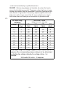
This battery charger is for use on a nominal 120-volt circuit, and has a •
grounding plug that looks like the plug illustrated in sketch A in Figure
8.8. A temporary adapter, which looks like the adapter illustrated in
sketches B and C, may be used to connect this plug to a two-pole recep-
tacle as shown in sketch B if a properly grounded outlet is not available.
The temporary adapter should be used only until a properly grounded