


6 © Copyright 2010 Schneider Electric All Rights Reserved. F-26642-8
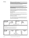
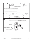
TYPICAL APPLICATIONS (wiring diagrams)
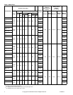
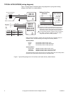
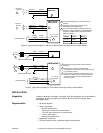
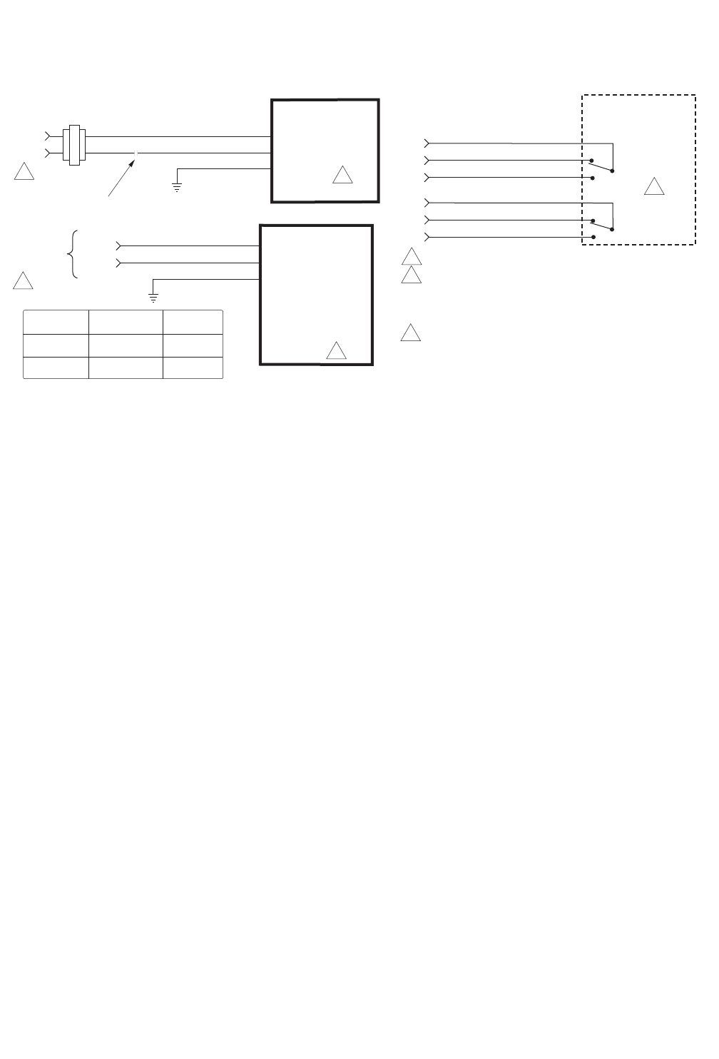
Figure-1 through Figure-3 illustrate typical wiring diagrams for spring return floating
actuators. See Table-1 for model selection.
MA4X-7153
MA4X-7073
MA4X-7153-502
MA4X-7073-502
2
1
1 Provide overload protection and disconnect as required.
2 Actuators mounted on separate shafts may be wired in
parallel. All actuator black wires are connected to the
transformer common and all red wires are connected to
the hot lead. Power consumption must be observed.
3 For end position indication, interlock control, fan startup,
etc., MA4X-715X-502, and MA4X-707X-502 models
incorporate two built-in auxiliary switches.
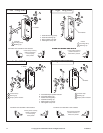
24 Vac Transformer
or 22-30 Vdc
Blk
Red
Com
Hot (+DC)
Line
Volts
Grn/Yel
SPST Control Contact
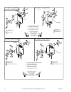
2
1
MA4X-7150
MA4X-7151
MA4X-7070
MA4X-7071
MA4X-7150-502
MA4X-7151-502
MA4X-7070-502
MA4X-7071-502
Wire No. 1
Wire No. 2
Com
Hot
L1 N
L2 H
120 Vac or
230 Vac
Grn/Yel
Org/Wht
Vio/Wht
Yel/Wht
NC
NO
3
Org
Vio
Yel
NC
NO
Com
Com
Aux Switch 1
Aux Switch 2
25 to 85°
Adjustable
5° Fixed
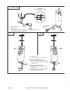
Aux Switches
MA4X-7XXX-502
Optional Auxiliary
Switches
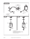
120 Vac White Black
230 Vac Blue
Brown
Voltage Wire 1 Wire 2
Figure-1 Typical Wiring Diagram for 24 Vac Basic and Double Auxiliary Switch Models.
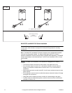
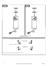
MX40-707X-502 and MX40-715X-502 units manufactured prior to the date code 0141
(October 6, 2001) used the following color coding for the auxiliary switches:
Auxiliary Switch 1
Orange: Fixed auxiliary switch common (com)
Yellow: Fixed auxiliary switch normally closed (NC)
Violet: Fixed auxiliary switch normally open (NO)
Auxiliary Switch 2
Orange/white: Adjustable auxiliary switch common (com)
Violet/white: Adjustable auxiliary switch normally closed (NC)
Yellow/white: Adjustable auxiliary switch normally open (NO)
The label information on these units is incorrect. If replacing these units, the auxiliary switch
operation of the replacement actuator will be per the product label.