F-26642-8 © Copyright 2010 Schneider Electric All Rights Reserved. 21
CHECKOUT
After the entire system has been installed and the actuator has been powered up, the
following check can be made for proper system operation. Check for correct operation of the
damper while actuator is being stroked.
1. Apply power to the actuator. Actuator and damper should be driven to their powered
position.
2. On the MA4X-7XXX-50X models, check for correct auxiliary switch operation.
3. Break power to the actuator. Actuator and damper should return to their normal, or
spring return position.
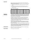
Table-5 Power Wiring Color Code.
THEORY OF
OPERATION
The actuators are mounted directly onto a damper shaft using a universal V-clamp. When
power is applied, the actuator rotates 95° to its powered position, at the same time tensing
the spring return safety mechanism. When power is removed, the spring returns the actuator
to its normal position. The actuators provide true mechanical spring return operation for
reliable, positive close-off on air tight dampers.
The MA4X-707X, MA4X-707X-502, MA4X-715X, and MA4X-715X-502 actuators are
equipped with a graduated position indicator showing -5° to 90°. The MA40-704X and
MA40-704X-501 are equipped with a graduated position indicator showing 0 to 1.
The MA40-704X-501 models are provided with 1 built in auxiliary switch. The SPDT switch
is provided for interfacing or signaling, for example, fan start-up. The switching function is
adjustable between 0° to 95° rotation (0 to 1 scale).
The MA4X-715X-502 and MA4X-707X-502 models are provided with 2 built in auxiliary
switches. The SPDT switches are provided for interfacing or signaling, for example, fan
start-up. The switching function is adjustable on one switch between 25° to 85° rotation and
the other switch is fixed at 5°.
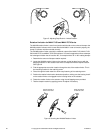
The MA41-707X-XXX and MA41-715X-XXX actuators are equipped with a manual override
mechanism. This allows the actuator to be manually positioned at any point between -5o and
85o. This mechanism is accessible on both sides of the actuator and can be used to ensure
tight close-offs for valves and dampers. The manual override should not be used while a unit
is powered or on units that are mounted in tandem.
MAINTENANCE Regular maintenance of the total system is recommended to assure sustained optimum
performance. The actuators are maintenance free.
FIELD REPAIR None. Replace with a functional actuator.
Part Number L1 L2
MA4X-7XX3
MA4X-7XX3-502
Red Black
MA4X-7XX0
MA4X-7XXX-502
Black White
MA4X-7XX1
MA4X-7XXX-502
Brown Light Blue


