


F-26642-8 © Copyright 2010 Schneider Electric All Rights Reserved. 19
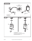
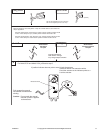
Auxiliary Switches The MA40-704X-501 series actuators include one built-in SPDT auxiliary switch which can
be used for interfacing or signaling (e.g., for fan start-up). The switch is adjustable between
0° and 95° of rotation (0 to 1 scale).
The MA4X-715X-502 and MA4X-707X-502 series actuators include two built-in SPDT
auxiliary switches which can be used for interfacing or signaling (e.g., for fan start-up). The
switch position near the normal (spring return) position is fixed at 5°. The other is adjustable
between 25° and 85° of rotation.
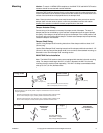
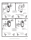
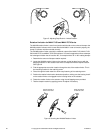
Adjusting the Switching Point
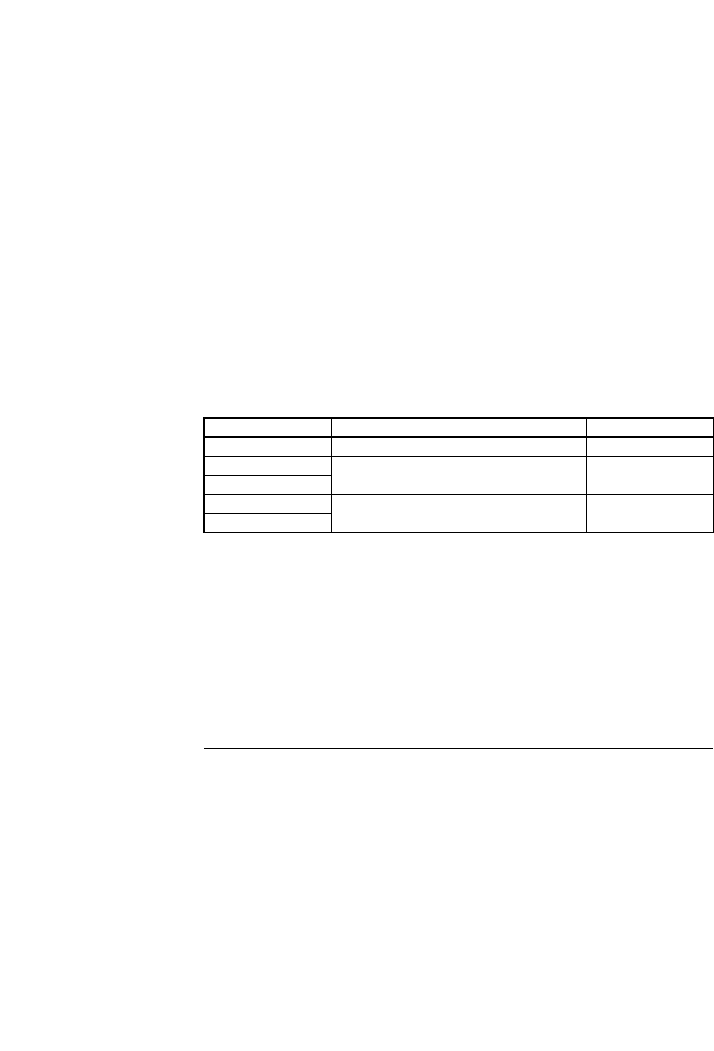
Refer to Table-4 for auxiliary switch rating.
Adjusting the switching point for MA40-704X-501
1. The actuator must be in its normal (spring return) position.
2. Use a flat screw driver to rotate the switch pointer until it is at the desired switch position
on the 0 to 1 scale.
Adjusting the switching point for MA4X-715X-502 or MA4X-707X-502
1. The actuator must be in its normal (spring return) position.
2. Insert a 1/8" allen wrench into the hex hole located in the center of the adjustable switch
pointer.
3. Rotate the wrench until the switch pointer is at the desired switch position in degrees,
from 25 to 85°.
Table-4 Auxiliary Switch Rating.
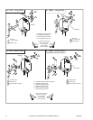
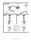
Rotation Limitation Rotation Limitation for MA40-704X Series
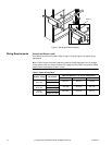
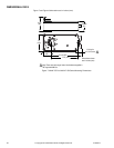
The Stop Block is used in conjunction with the tab on the universal clamp or the AM-709
position indicator. In order to function properly, the clamp or indicator must be mounted
correctly.
The Stop Block controls the rotational output of the MA40-704X and MF40-704X-501
actuators. It is used in applications where a damper has a designed rotation that is less than
90°, for example with a 45° or 60° rotating damper.
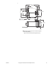
1. Determine the amount of damper rotation required. The actuator stop block provides
limited rotation from 40° to 95°.
2. Loosen the screw securing the stop block to the actuator.
Note: The actuator is shipped with the Stop Block mounted to the “L” side. If the damper
application requires the “R” side face the installer, simply remove the Stop Block and screw
and move it to the new location.
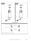
3. Slide the stop block into position, so that its edge lines up with the degree graduation
on the actuator face which corresponds with the required rotation. See Figure-5.
4. Secure the stop block in place.
5. Test the damper rotation by applying power. Re-adjust if necessary.
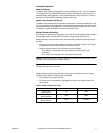
Part Number Voltage Resistive Load Inductive Load
MA40-7043-501 24 Vac 6A 1.5A
MA40-7040-501
250 Vac 6A 1.5A
MA40-7041-501
MA4X-707X-502
250 Vac 7A 2.5A
MA4X-715X-502