


F-26642-8 © Copyright 2010 Schneider Electric All Rights Reserved. 17
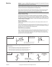
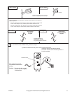
Jackshaft Installation
(MA40-704X Series)
The MA40-704X actuator is designed for use with jackshafts up to 3/4" (19 mm) in diameter.
In most applications, the MA40-704X actuator may be mounted in the same manner as a
standard damper shaft application. If the jackshaft diameter is larger than 5/8" (16 mm) in
diameter, the optional AM-710 universal clamp must be used.
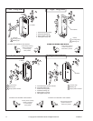
(MA4X-715X and MA4X-707X Series)
The MA4X-715X and MA4X-707X actuators are designed for use with jackshafts up to 1.05"
(27 mm) in diameter. In most applications, the actuator may be mounted in the same manner
as a standard damper shaft application. If the jackshaft diameter is larger than 3/4" (19 mm)
in diameter, the optional AM-687 universal clamp must be used.
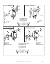
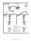
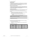
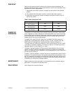
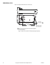
Multiple Actuator Mounting
If more torque is required than one actuator can provide a second actuator may be mounted
to the damper shaft, using the AM-673 multiple mounting bracket. See Figure-4.
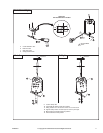
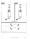
Multiple actuators may be powered from one transformer provided the following rules are
followed:
• The total current draw of the actuators (VA rating) is less than or equal to the rating of
the transformer and less than the rating of the control circuit.
• Polarity on the secondary of the transformer is strictly followed.
– All L2 wires from all actuators are connected to the common lead on the
transformer.
– All L1 wires from all actuators are connected to the hot lead.
Caution: Mixing the L2 and L1 wires on one lead of the transformer may result in erratic
operation or failure of the actuator and/or controls.
Caution: Do not attempt to use the manual override with actuators mounted in tandem.
Damage to the gear train may occur.
Multiple actuators positioned by the same control signal may be powered from multiple
transformers provided the following rules are followed:
• The transformers are properly sized.
• All L2 wires from all actuators are tied together and tied to the negative lead of the
control signal.
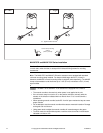
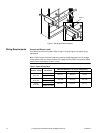
Table-2 Power Wiring Color Code.
Part Number L1 L2
MA4X-7XX3
MA4X-7XX3-502
Red Black
MA4X-7XX0
MA4X-7XXX-502
Black White
MA4X-7XX1
MA4X-7XXX-502
Brown Light Blue