11
11
1
X
15
S4359146
3-3. Placing the Unit Inside the Ceiling
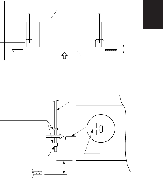
(1) When placing the unit inside the ceiling, deter-
mine the pitch of the suspension bolts using the
supplied full-scale installation diagram. (Fig. 3-4)
The size of the opening for the indoor unit can be
confirmed by attaching the full-scale installation
diagram beneath the unit. (Fig. 3-4)
Tubing and wiring must be laid inside the ceiling
when suspending the unit. If the ceiling is already
constructed, lay the tubing and wiring into posi-
tion for connection to the unit before placing the
unit inside the ceiling.
(2) The length of suspension bolt must be appropri-
ate for a distance between the bottom of the bolt
and the bottom of the ceiling of 19/32 in. or more
as shown in Fig. 3-4.
(3) Thread the 2 hexagonal nuts (field supply) and
washers onto the 4 suspension bolts as shown in
Fig. 3-5.
Use 2 sets of nuts and washers (upper and
lower), so that the unit will not fall off the suspen-
sion lugs.
(4) Remove the protective cardboard used to protect
the fan parts during transport.
(5) Adjust the distance between the unit and surface
of the ceiling. (1-7/8 in.) (Fig. 3-4)
Fig. 3-4
Fig. 3-5
19/32 inch or more
1-7/8 inch
2040_X_I
Full-scale installation diagram
(printed on a cardboard packing)
Full-scale installation
diagram
1971_X_
I
Nuts and washers
Double nuts
(Use above and below)
Suspension bolt
Suspension lug
Upper
Lower
Notch
1-7/8 inch


