


RoyalTek Confidential
7
RET-3570LP User Manual
impedance to connect RF_IN to the antenna or any antenna connectors that you prefer.
(Impedance 50
Ω)
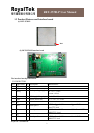
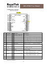
(5) FM_RF_IN:
Connecting to the antenna has to be routed on the PCB. The transmission line must control
impedance to connect FM_RF_IN to the antenna or any antenna connectors that you prefer.
(Impedance 50
Ω)
(6) Power:
Connect V_GPS_3V3 and V_TMC_3V3 pin to DC 3.3V. The power supply must add a
bypassing capacitor (10uF and 1uF) to reduce the noise from power supply and increase
power stability.
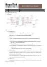
(7) Active antenna bias voltage:
The Vcc_RF_OUT pin (pin 20) provides voltage 2.85V. If you use an active antenna, you
can connect this pin to V_ANT_IN pin (pin 19) for providing bias voltage of an active
antenna. The bias voltage will run through GPS_RF_IN pin to provide active antenna bias
voltage from Vcc_RF_OUT pin.
If your bias voltage of an active antenna isn’t 2.85V, you can input bias voltage that you
need to V_ANT_IN pin (pin 19). The input bias voltage will run through GPS_RF_IN pin
to provide active antenna bias voltage from V_ANT_IN pin.
PS:
(
Ⅰ). The maximum power consumption of active antenna is around 85mW.
(
Ⅱ). The input gain ranges from 12 to 26dB.
(8) GPIO:
The GPIO pin is recommended to connect to serial resistance(220
Ω), if the GPIO function
is used.
If GPIO function is not used, it won’t connect anything.