


RoyalTek Confidential
12
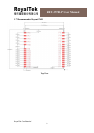
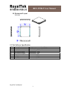
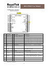
RET-3570LP User Manual
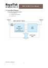
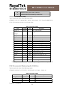
TXA
This is the main transmitting channel and is used to output navigation and measurement data
to SiRFdemo or from user’s application.
TXB
For user’s application.(Not current use).
RF_ON
This pin indicates the status of RF voltage.
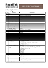
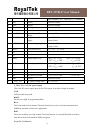
V_TMC_3V3 (+3.3V DC power Input)
This is the DC power supply input pin for TMC function. It provides voltage for TMC section
of the module.
AUDIO_R
This pin is the function of audio right channel output.
AUDIO_L
This pin is the function of audio left channel output.
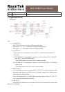
FM_RF_IN
This pin can receive FM analog signal. The trace on the PCB from the antenna(or antenna
connector) has to be controlled impedance line (Micro strip at 50
Ω).
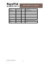
GPS_RF_IN
This pin can receive GPS analog signal. The trace on the PCB between the antenna(or antenna
connector) has to be a controlled impedance line (Micro strip at 50
Ω).
V_ANT_IN
This pin is reserved as external DC power supply input for an active antenna.
If using 2.85V active antenna, the pin 20 has to be connected to pin 19.
If using 3.3V or 5V active antenna, this pin has to be connected to 3.3V or 5V power supply.
PS: The current must be
≦100mA and voltage ≦12V, if external power supply is used.
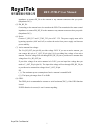
VCC_RF_OUT
This pin can provide power 30mA@2.85V for an active antenna.
RESET
This pin provides an active-low reset input for the board. It causes that the board resets and
starts to search for satellites. If RESET pin is not used, it won’t connect anything.
PPS
This pin provides one pulse-per-second output from the board, which is synchronized to GPS
time. This is not available in Trickle Power mode.
V_RTC_3V3 (Backup battery)
This is the battery backup input that powers the SRAM and RTC when the main power is
removed. Typical current draw is 10uA.