


RDR-3200 User Manual
5. Interface
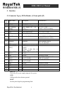
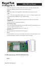
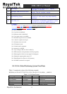
5.1 Connector Type:20 Pin Header,2.0 mm pitch (J2)
Pin
NO
Signal Name I/O Description Characteristics
1 N.C None connector
2 GPS 5V I +5V DC Power Input DC +5V ± 5%.
3 RTC (Backup
voltage)
I User Supply DC +2.6 ~
+3.6V
DC +2.6 ~ +3.6V.
Current ≤ 10uA w/o battery
4 GPS 5V I +5V DC Power Input
5 Reset I Reset (Active low)
8.0 2.3V V VV <>
IH IL
6 Boot I Boot mode
VVVV
ILIH
855.00.3V- 995.115.3 ≤≤≥≥
7 Back (Reverse) I Forward or Back Forward (Hi level :>2V)
Backward (Lo level: <0.8V)
8 N.C None connector
9 Odometer I Odometer Input frequency<4k HZ
Vih > 2V Vil<0.8V
10 GND G Ground Reference Ground
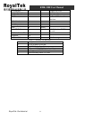
11 TXD1 (SiRF 3
TXD1)
O NMEA (transmit) Car PC
(UAR1)
2
4800bps, 8 data bits, no
parity, 1 stop bit
VVVVV
OLOH
715.0 375.285. ≤≥≥
12 RXD1 (SiRF 3
RXD1)
I NMEA (Receive) Car PC
(UAR1)
3 VVVVV
ILIH
855.00.3V- 995.115. ≤≤≥≥
13 GND G Ground Reference Ground
14 TXD2 (SiRF 3
TXD2)
O Can bus data (transmit) Vih > VDD-0.1V Vil<0.6V
Car PC (UAR2) VDD:3.3V for MCU
15 RXD2 (SiRF 3
RXD2)
I Can bus data (Receive) Vih > 2V Vil<0.8V
Car PC (UAR2)
16 GND G Ground Reference Ground
17 GND G Ground
18 GND G Ground Reference Ground
19 N.C NC
20 N.C NC
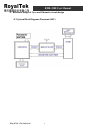
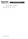
GPS_5V
This is the DC power supply input pin for system. .
GND
GND provides the reference ground .
BOOT
Set this pin to high for programming flash.
RoyalTek Confidential
8