


RDR-3200 User Manual
4.2 Application Circuit
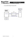
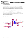
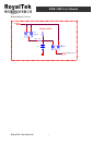
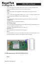
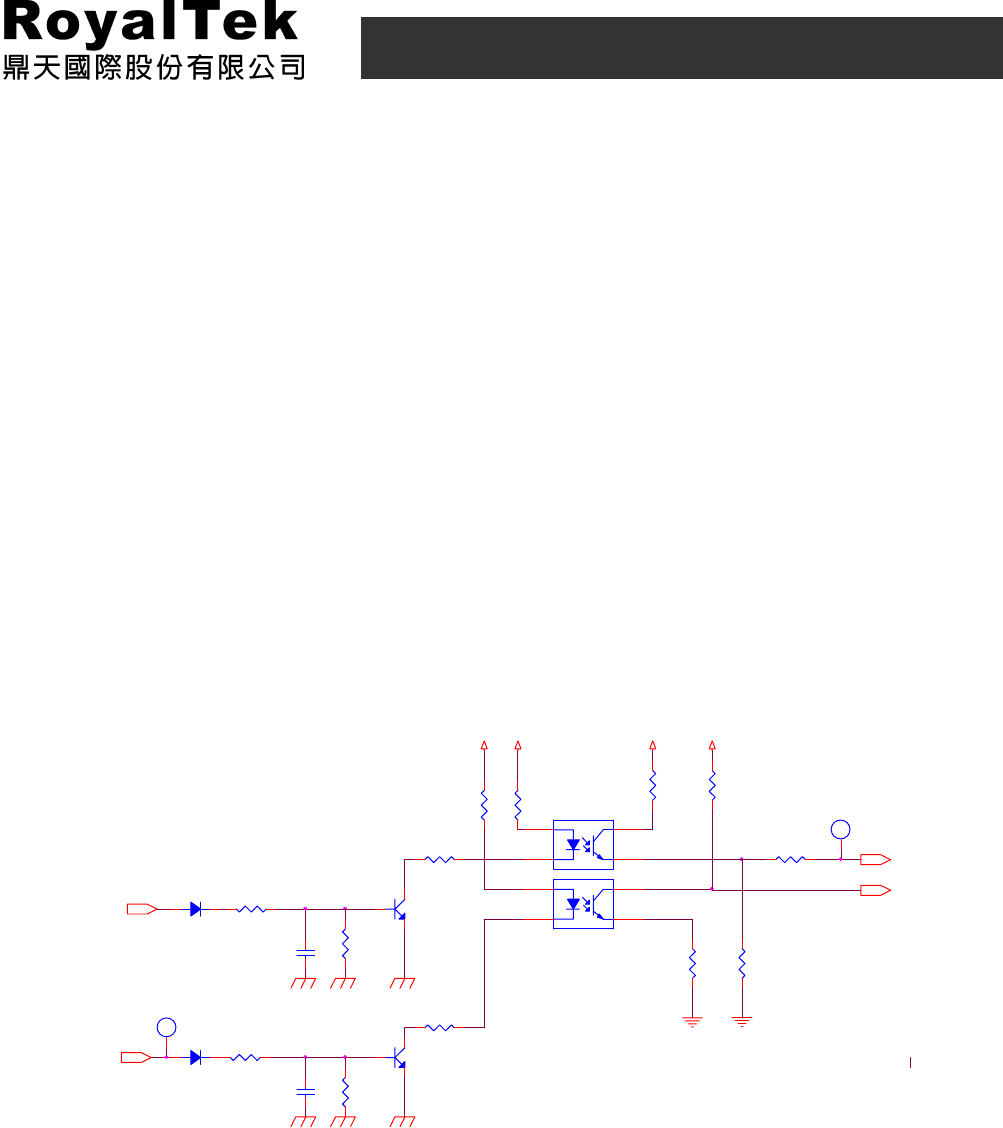
Figure 1 illustrates the proposed schematic diagram of Gyro, odometer and RDR-3200.
RDR-3200 supports the Gyro, Panasonic. Please care about the ground partition design
among Gyro circuit, RDR-3200 and odometer input. It would be better to use 2 kinds of
ground.
The input of odometer is around 12V typically. It transfers the voltage level to
accommodate the I/O voltage level of RDR-3200. The photo coupling transistors also
isolate the noise of car from the RDR-3200 system.
The power of the gyro is 5Vwhich is different from the power of RDR-3200. Please use a
separate analog ground for gyro. And please keep high speedy signal away from the signal
path of gyro and power when doing layout.
Figure 1.
Odometer/Reverse Circuit
V_5V
R19
0
V_5V
C11
0.01uF
U4
LTV817S
2 3
41
D1
1N4148
R15 20
V_3V3V_3V3
R17 22K
Q2
2SC2412K
3
2
1
R12
220
R11
1k
R13
220
Odometer
D2
1N4148
R23
0
Q1
2SC2412K
3
2
1
TP32
1
1
R24 22K
TP31
1
1
reverse_A/D
R25
100K
Reverse
R14
0
R18
270
R22
100K
C10
0.01uF
odometer_A/D
U5 LTV817S
2 3
41
R47
0
RoyalTek Confidential
6