


8-1
-2
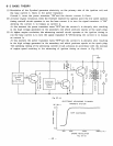
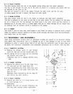
PILOT SYSTEM
The pilot system feeds the fuel to the engine during idling and low- speed operation.
The fuel
is
fed through the main
jet
to the pilot jet, where
it
is
metered, and mixed with
the
air metered
by
the pilot air jet.
The fuel- air mixture is fed to the engine through the pilot outlet and the by- pass.
At idling speed, the fuel is mainly fed from the pilot outlet.
8-
1-3
MAIN
SYSTEM
The main system feeds the fuel to the engine at medium- and high-speed operation.
The fuel
is
metered by the main jet and fed to the main nozzle. The air metered
by
the main
air jet is mixed with the fuel through the bleed holes in the main nozzle, and the mixture
is
atomized out of the main bore. It
is
mixed again with the air taken through the air cleaner into
an
optimum fuel-air mixture, which
is
supplied to the engine.
8-
1
-4
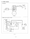
CHOKE
The choke
is
used for easy start when engine
is
cold. When the starter
is
operated with a closed
choke, the negative pressure applied to the main nozzle increases and draws much fuel accordingly
:
thus easily start up the engine.
8-
2
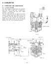
DISASSEMBLY
AND
REASSEMBLY
Apart
from
mechanical failures, most
of
carburetor troubles are caused
by
an incorrect mixing
ratio, which may arise mainly due to a clogged
up
air or fuel passage in jets, or fuel level
variations.
In
order to assure proper flow of air and fuel, the carburetor must be kept clean at
all times. The carburetor disassembly and reassembly procedures are as follows
:
(See
Fig.
68.)
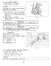
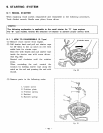
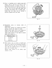
8-2-1
THROTTLE
SYSTEM
(1)
Remove the philips screw
(1)
and
throttle
123
valve
(2),
and pull out the throttle-> shaft
(3).
(2)
The spring
(4)
can be taken out by removing
the throttle stop screw
(5).
*Exercise care not to damage throttle valve
ends.
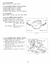
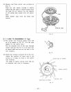
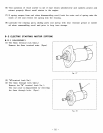
8-2-2
CHOKE
SYSTEM
(1)
Remove the philips screw
(6)
and choke valve
(2)
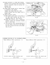
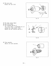
When reassembling the choke shaft, make sure
@“----
23
(71,
and pull out the choke shaft
(8).
that the cutout in the choke valve faces the
main air jet.
19
Meantime, when reassembling set the rings
(9)
and
(10)
at the right position.
l7”---i
LZ2
16
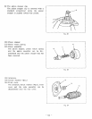
8-2-3
PILOT
SYSTEM
(1)
Remove the pilot jet
(1
l).,
using correct tool
(2)
Reassembly
to avoid damage to it.
Tighten the pilot jet securely. Otherwise, the
fuel may leak, causing engine malfunction.
13
<a
18
&
12
“--&
Fig.
68
-
47
-