


To wire the switch to the battery…
continued from preceding page
to the positive terminal on the vehicle’s battery.
Note: if the vehicle’s battery must be disconnected for
towing and a battery disconnect device has been installed,
make certain that the red wire is connect to the positive
side of the battery disconnect device. In this manner, 12V
+
will be present when the battery is disconnected.
for BrakeMaster wiring…
• Follow steps one through five above.
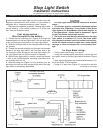
• Using the spade connectors, connect the red and green
wires to the stop light switch terminals (Figure A).
• Now, using a butt connector, connect the green wire to
the “hot” wire in the BrakeMaster motorhome monitor.
• Using a 10 amp fuse (Figure A), connect the red wire to
the positive terminal on the vehicle’s battery.
Second wiring method —
Wire the switch to the fuse box…
Note: Some newer vehicles may have an electronic
“retained accessory power” feature. Refer to the owner’s
manual, or the manufacturer, to determine if the vehicle
is so equipped.
With this feature, the electronic accessories continue to
function normally for about ten minutes after the ignition
key is turned off, as if the key were in the “ACC” position.
Then, the electronic accessories will turn off.
If the vehicle has a retained accessory power feature, do
not use this method — instead, wire the stop light switch
to the battery.
If the brake lights do not function when the ignition is
turned to the “tow” position, the stop light switch can be
wired to the vehicle’s fuse box, instead of to the battery.
Use the instructions below to connect the stop light
switch to the fuse box.
• Follow steps one through five above.
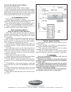
• Using the spade connectors, connect the red and green
wires to the stop light switch terminals (Figure B).
• For Even Brake — connect the green wire to the termi-
nal marked “1” on the Even Brake ICX transmitter (Figure
A).
For BrakeMaster — using a butt connector, connect the
green wire to the “hot” wire in the BrakeMaster motorhome
monitor.
• Using a 10 amp fuse, connect the red wire to a fuse
that is constantly “hot” when the ignition key is in the “tow”
position (Figure B).
With a fuse tap, attach the wire to the “cold” side of the
fuse socket.
Figure B
Towing and Suspension Solutions
ROADMASTER, Inc. • 6110 N.E. 127th Ave. • Vancouver, WA 98682 • 800-669-9690 • Fax 360-735-9300 • roadmasterinc.com
Test for proper function
After the stop light switch has been installed, test for
proper function…
• With a test light, verify 12VDC
+
on both spade con-
nectors with the brake pedal depressed.
• With a test light, verify 12VDC
+
on only one spade
connector with the brake pedal released.
• With the vehicle’s engine on, verify that the brake
lights illuminate only when the brake pedal is depressed.
When the installation is complete, verify that the
brake pedal retracts fully.
Unless they are installed correctly, the bracket and/
or other kit components may impede the movement of
the brake pedal.
If the brake pedal does not retract fully, the brakes
will be applied continuously, which may cause severe
tire and/or brake system damage, as well as other con-
sequential, non-warranty damage.
Failure to follow these instructions may cause prop-
erty damage, personal injury or even death.