


Stop Light Switch
Installation Instructions
ROADMASTER, Inc. • 6110 N.E. 127th Ave. • Vancouver, WA 98682 • 800-669-9690 • Fax 360-735-9300 • roadmasterinc.com
I
nstall this kit if the brake lights do not function when the
ignition is turned to the “tow” position, or if the vehicle is
equipped with a “retained accessory power” feature.
There are two installation methods — the stop light switch
can be wired to: 1) the vehicle’s battery; or 2) to the fuse
box. See the directions below.
First wiring method —
Wire the switch to the battery…
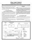
1. Thread the first adjusting nut (Figure A) through the
threaded portion of the stop light switch, with the open side
of the nut facing the terminals on the stop light switch.
2. Slide the threaded side of the stop light switch through
the bracket.
3. Thread the second adjusting nut through the threaded
portion of the stop light switch, with the open side of the
nut facing the white plunger on the stop light switch. (Do
not fully tighten the nut until the switch is installed.)
4. With the stop light switch in position, attach the bracket
— refer to the vehicle-specific mounting instructions that
are included with this kit.
5. With the brake arm (Figure A) fully retracted, turn the
adjusting nuts until the white plunger at the end of the stop
light switch is completely depressed.
All specifications are subject to change without notice.
Figure A
85-3483-03 12-09
The stop light switch must be installed as directed
above…
• The plunger must be completely depressed against
the brake arm. Otherwise, it may cause a false brake
light signal at the BrakeMaster motorhome monitor, or
a “Not operational — Brake pedal is depressed” signal
at the Even Brake motorhome monitor.
• The brake arm must be fully retracted when the stop
light switch is installed. If it is not, the brake pedal
may depress the towed vehicle’s brakes continuously,
which will cause excessive brake wear, brake system
damage or other consequential, non-warranty dam-
age.
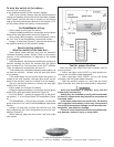
for Even Brake wiring…
• Follow steps one through five above.
• Using the included spade connectors, connect the red
and green wires to the stop light switch terminals (Figure
A).
• Now, connect the green wire to the terminal marked “1”on
the Even Brake ICX transmitter.
• Using a 10 amp fuse (Figure A), connect the red wire
continued on next page