


27
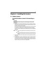
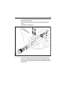
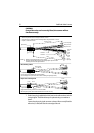
9. Connect the red “+”and black “-” power cores (7).
If you have a 10 m or light 15 m inter-unit cable, there is one pair of cores.
Connect the red cable lead to one of the terminal sockets marked “+”, and
the black cable lead to one of the sockets marked “-”.
If you have a heavy 15 m inter-unit cable, there are two pairs of cores. Con-
nect the red cable leads to the terminal sockets marked “+”, and the black
cable leads to the terminal sockets marked “-”, with one lead in each socket.
The terminal clamps (8) are operated using a screwdriver (9), as shown in the
inset diagram on the previous page.
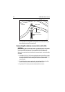
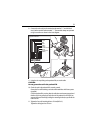
10. Secure the nut (1) on the watertight gland (2), making sure that it grips the
cable’s outer sheath.
11. Secure the cable with the top clamp (11), using the two screws (12) provided.
Ensure that the clamp goes around the exposed wire braid, and that the wire
braid makes contact with the earthing clamp. Tighten the screws until the top
clamp deforms
just enough
to contact the lower earthing clamp (see inset).
CAUTION:
It is essential that the drain tube is fitted and that the nut on the
watertight gland is adequately tightened. If this is not done,
water could become trapped in the scanner and cause irreparable
damage.
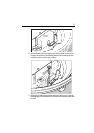
12. Tighten the securing nut (1) again to ensure a waterproof seal.
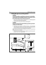
13. If you have a 4D scanner, replace the inner cover over the connectors.
14. Untie the cord from the scanner cover, and coil it up in the base of
the scanner unit so that it cannot foul the rotating antenna.
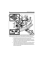
15. Replace the scanner cover, aligning the mark on the cover with the mark on
the scanner base above the cable gland, and tighten the 4 or 7 captive screws.
Do not over-tighten these screws.