


ST30 Compass Installation and Operation Handbook
12
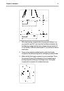
3. Run the cable back to the display head, fixing the cable at regular
intervals with cable clamps/ties.
4. Crimp the spade connectors to the five wires from the
compass cable.
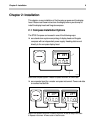
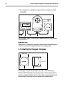
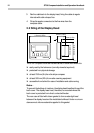
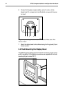
2.2 Siting of the Display Head
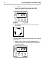
LOCK
COMPASS
LOCK
HEADING
AVERAGE
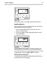
110mm (4.33in)
42mm (1.65in)
24mm (1.0in)
56mm (2.20in)
88mm (3.46in)
D1788-1
The ST30 Compass should be installed above or below deck where it is:
❏ easily read by the helmsman (normally viewed at eye level)
❏ protected from physical damage
❏ at least 230mm (9in) from the ships compass
❏ at least 500mm (20in) from radio receiving equipment
❏ accessible from behind for ease of installation and cable running
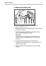
Notes...
To prevent the build-up of moisture, the display head breathes through the
back cover. The display head must, therefore, be mounted where the
back cover is protected from direct contact with water.
The rear case is fitted with a foam gasket to form a water-tight seal
between the display head and the installation bulkhead. Under no circum-
stances must silicone sealants be applied to this gasket.