


2
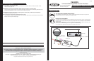
Wiring Connections
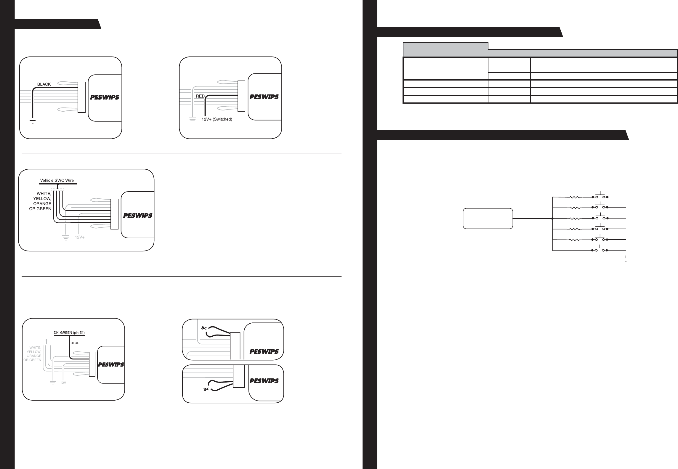
Step 1.
Connect the BLACK
wire to ground (-).
Verifi cation: Wire
or location reg is ters
a con stant (-) when
probed.
Step 2.
Connect the RED wire
to switched +12V.
Verifi cation: Wire reg-
isters +12V when the
ignition key is turned
to the ACC or ON posi-
tions.
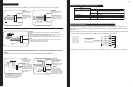
Step 3.
Connect the ap pro pri ate in ter face wire (WHITE, YELLOW, ORANGE or
GREEN).
• Refer to the Identifi cation and Connection Chart. Locate the vehicle and
note the SWC wire color in the “In ter face Wire Color” column.
• Note the vehicle wire color and lo ca tion in for ma tion in the “Iden ti fi ca tion”
col umn.
Note: You will only connect ONE of these wires. The other 3 wires will not
be used. Cut and insulate the un used wires.
• Connect the wire as indicated in the chart.
Note: Only 3 wires will be used during installation. Only GM vehicles programmed for version #4, will use 4 wires.
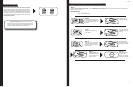
Step 4a.
Con nect the BLUE
serial data wire.
Connect this wire
ONLY on GM
pas sen ger ve hi cles (no
trucks or SUVs) with
airbags AND steering
wheel heater controls.
For all other vehicles,
cut and insulate the
BLUE wire.
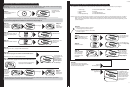
Step 4b.
If instructed by the
Vehicle Application
Guide, cut the
BROWN wire loop and
insulate both halves.
Step 4c.
If instructed by the
Vehicle Application
Guide, cut the VIOLET
wire loop and insulate
both halves, or place a
resistor in-line of wires.
Note: Step 4a is for vehicles made by
General Motors that are programmed
for version #4 only. If no con nec tions is
necessary, proceed to Step 4b.
Step 4
If necessary, perform the following operations as indicated by the notes in Identifi cation and Connection Chart.
7
11-29-05
Appendix A: Known Incompatible Vehicles
Vehicle
Make(s) Year(s) Model(s)
BMW All All with factory-activated cellular phones
All with 5-volt SWC data wire at the steering column
2002-2003 5-Series w/navigation
Mercedes-Benz All All vehicles
Toyota All-2003 Sienna
Volkswagen 2002-up All vehicles
Steering Wheel
Interface
47
150
560
1000
1500
Connect SWI white
wire to resistors
47 = yel, vio, blk
150 = brn, grn, brn
560 = grn, blu, brn
1000 = brn, blk, red
1500 = brn, grn, red
3900 = org, wht, red
5100 = grn, brn, red
Some vehicles have a seperate wire for each of the steering wheel buttons. Use this resistor kit for the steering wheel
push buttons that do not already have a resistor network connected to them. Examples are Nissan and Harley Davidson
motorcycles.
Connect a resistor to each side of a push button and connect the other ends of the resistor all together. Connect the SWI-
X to these resistors. On the Harley Davidson, one button can be connected directly to the SWI-X.
By putting two or more resistor in series, you can come up with additional values. Ex. 150 + 1000 + 1500 = 2650ohms.
Appendix B: Resistor Kit