MX80L Series Product Manual Chapter 3 - How to Use the MX80
Parker Hannifin Corporation
30
Total mass = 0.46 kg (Payload mass = 250 grams + Carriage mass = 213 grams)
Application Speed = 500mm/sec
Available peak force at .25 m/sec = 11.8 N (See Chapter 2, Force / Speed Curve)
Maximum Obtainable Deceleration Rate
Thus: F = ma Æ a = F/m Æ a = 11.8N / 0.46kg Æ 25.6 m/sec
2
Now, calculate the Deceleration Distance for linear deceleration:
First… find the Deceleration time:
Ta = Max Velocity / Deceleration Rate
Ta = .50 m/sec / 25.6 m/sec
2
Æ 0.020 seconds
Second… find the Deceleration Distance:
Distance = ((Max Velocity) * (Ta)) / 2
Distance = ((500 mm/sec) * (0.020)) / 2 Æ 5.0 mm
This means that both the positive and negative limit switch targets must be moved inward by 5.0 mm.
The limit deceleration rate should be set to 25.6 meters/sec
2
. Using the supplied limit flag sheet cut two
5.0mm long strips from the appropriate white or black (depending on configuration) marked Limit/Home
Adjustment overlay decal and follow the procedure for changing the limits.
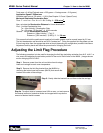
Adjusting the Limit Flag Procedure
The following procedure is to be used for changing the limit flag (switching activation from N.O. to N.C. or
vice versa) and adjusting the activation position of the end of travel limits on the MX80: (Images shown
are for changing H3L2 to H2L3
Step 1: Remove power from the unit and allow time for stage
base and carriage to reach room temperature
Step 2: Remove the limit flag bracket from the MX80L by
removing the button head cap screws (BHCS) that secure the
bracket to the side of the carriage.
Step 3: Gently slide the bracket from out from under the carriage.
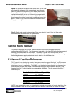
Step 4a: To adjust limits to increase travel: With a razor, cut and remove
the desired amount of protective sticker and magnet which equals the
amount of desired travel increase.
Daedal Division
Irwin
,
Penns
y
lvania


