MX80L Series Product Manual Chapter 3 - How to Use the MX80
Parker Hannifin Corporation
Daedal Division
Irwin
,
Penns
y
lvania
26
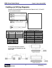
Cabling and Wiring Diagrams
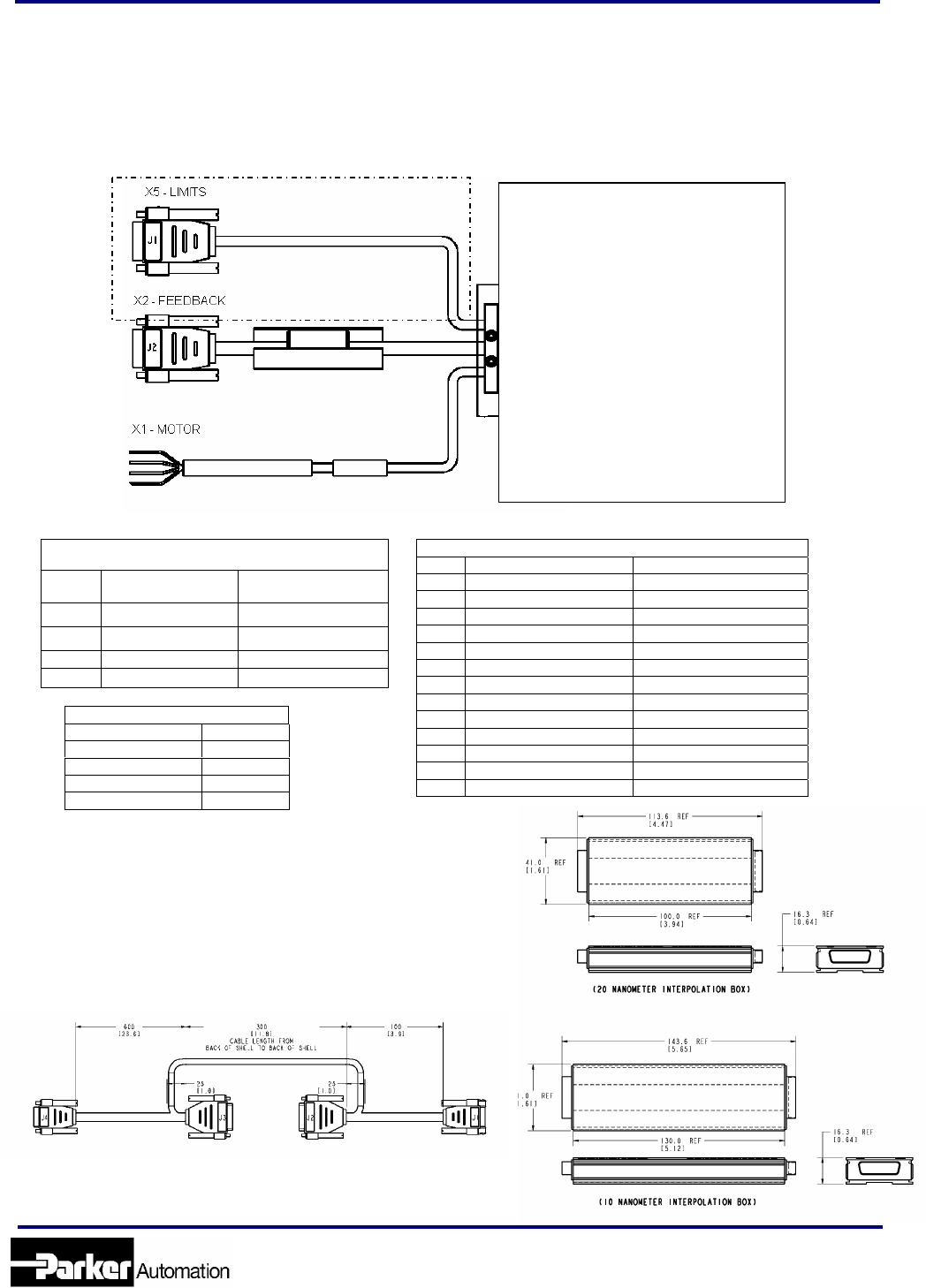
Connector Pin Out and Extension Cable Wire Color Codes for the 5, 1, 0.5 and 0.1
micron resolution encoders
Not included with
[H1][L1] option
X2 – FEEDBACK-HALL CONNECTOR
PIN FUNCTION WIRE COLOR
1 Encoder Z+ ORANGE
2 Encoder Z- BROWN
3 GND BLACK
5 +5V RED
6 Temperature- YELLOW/BLACK
7 Encoder A+ WHITE
8 Encoder A- YELLOW
9 Hall#1 WHITE/BROWN
10 Temperature+ YELLOW/RED
11 Encoder B- BLUE
12 Encoder B+ GREEN
13 Hall#2 WHITE/ORANGE
14 Hall#3 WHITE/VIOLET
X5 – LIMITS CONNECTOR
PIN FUNCTION WIRE COLOR
1 GND BLACK
6 + End of travel ORANGE
7 - End of travel BLUE
8 Home GREEN
X1 – MOTOR LEADS
WIRE COLOR DRIVE
RED U
WHITE V
BLACK W
GREEN GND
The 10 and 20 nanometer resolution
encoders have an interpolator box and
bypass cable


