


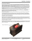
Copyright 2003 OutBack Power Systems, Inc. FX & VFX Series Inverter/Charger System Installation & Programming Manual
19009 62
nd
Ave NE, Arlington WA 98223 USA 900-0027-1
Tel 360 435 6030 Fax 360 435 6019
Rev 7.2 08/26/05 Page 5
IMPORTANT SAFETY INSTRUCTIONS
Installation Guidelines
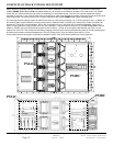
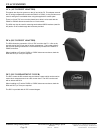
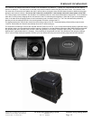
This manual contains important instructions for the OutBack FX series inverter/charger system with the software which allows classic
(two FX’s in series), parallel and series/parallel stacking of two to ten FX’s for higher power and/or higher voltage systems.
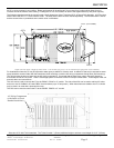
1 All of the AC wiring to the AC terminals is to be torqued to 30 inch-pounds (equivalent to 2.5 foot-pounds or 3.4 Nm).
Wiring to these terminals must meet requirements of the National Electric Code (NEC). The terminals will accept up to 6AWG.
Use copper conductors only with insulation rated for 75˚ C. See the AC WIRING CONNECTIONS section of this manual for more
information.
2 Torque the DC connections to 60 inch-pounds (equivalent to 5 foot-pounds or 6.8 Nm). Cables to these terminals must use
a crimp on type ring terminal or compression type lug. Cable must meet the requirements of the National Electrical Code. Use
of large gauge cables (2/0 or 4/0 AWG) or larger is advisable to reduce losses and ensure high performance of the FX. Cables of
too small a gauge can result in poor performance and even damage the FX. Keep the cables together as much as possible and
ensure that both cables pass through the same knockout and conduit fittings and to allow the inductive currents to cancel.
3 For equipment grounding hook up, see the system configuration sections in this manual. Non-mobile (“M”) FXs are intended to
be installed as part of a permanently grounded electrical system per the NEC. Mobile FXs include integral “Ground-switching”
mechanisms. Please refer to the MOBILE FX INFORMATION section of this manual for proper grounding instructions.
4 AC overcurrent protection for all connections must be provided by others as part of the installation.
5 DC battery circuit overcurrent protection must be provided by others as part of the installation. OutBack offers 100, 175 and 250
amp DC breakers (part number OBDC-XXX) which can be used with the FX. For “Mobile” installations, OutBack includes a stud
mounted fuse which can be connected directly to the positive DC terminal of the FX – it is available in 100, 175 and 250 amp
sizes (part number SMF-XXX). The stud mounted fuses require a 10mm hole in the battery terminal lug. US lugs are typically
3/8” diameter. Light filing may be required to insure proper fit of the nut shoulder into the lug hole.
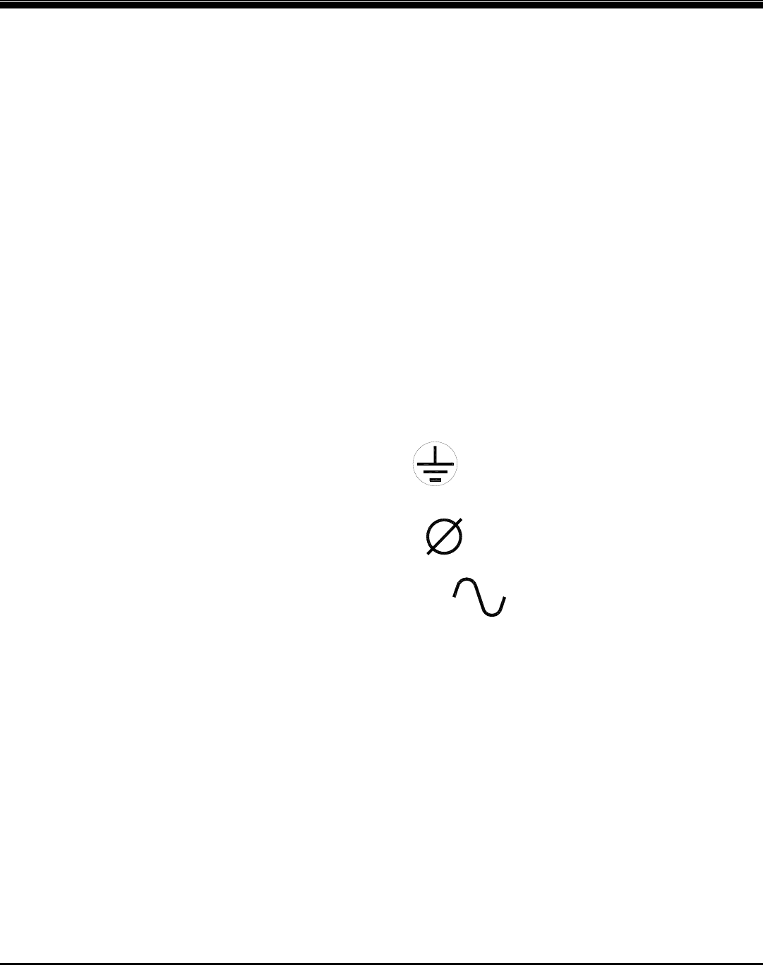
6 The equipment ground on the inverter is marked with this symbol:
7 This inverter has a single phase output. It is marked with this symbol:
8 This inverter puts out a sine wave waveform. It is marked with this symbol:
9 CAUTION: To reduce the risk of fire, connect only to a circuit provided with 60 amp maximum branch-circuit overcurrent
protection in accordance with the National Electrical Code, ANSI/NFPA 70.
10 WARNING: To reduce the risk of fire, do not connect a single FX to both hot legs of a 120/240 VAC AC load center having multi
wire (common neutral) branch circuits connected. Use two FX’s wired in a series configuration or the addition of an X-240
autotransformer if you are connecting to a 120/240 VAC multi wire system.
11 IMPORTANT: Always install the battery terminal covers, even in systems that include the DCC (DC Compartment Cover).